Hi TI Team,
We are develop feature for camera using our customer board.
TDA4EVB use I2C_6 bus for CSI0/CSI1 camera setting.
but We modify Our board use I2C_2(CSI0) / I2C_0(CSI1) for camera init,
I followed the instructions like this post but it doesn't work: https://e2e.ti.com/support/processors-group/processors/f/processors-forum/986493/tda4vm-how-to-change-csi-camera-i2c-instance-in-vision_app
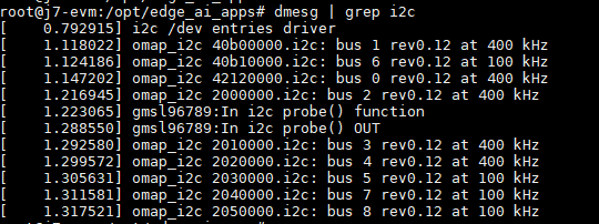
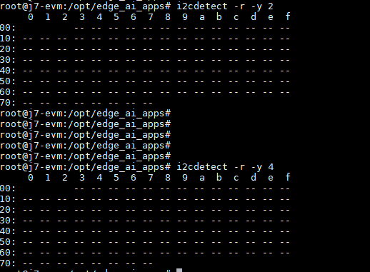
I can not read/write i2c by i2c_0 and i2c_2.
I changed are as below, Could you help us correctly?
Thank You.
1. Disable I2C0 and I2C2 in the device tree "k3-j721e-common-proc-board.dts"
&main_i2c0 {
	pinctrl-names = "default";
	pinctrl-0 = <&main_i2c0_pins_default>;
	clock-frequency = <400000>;
	status = "disabled";
	exp1: gpio@20 {
		compatible = "ti,tca6416";
		status = "disabled";
		reg = <0x20>;
		gpio-controller;
		#gpio-cells = <2>;
	};

	exp2: gpio@22 {
		compatible = "ti,tca6424";
		status = "disabled";
		reg = <0x22>;
		gpio-controller;
		#gpio-cells = <2>;

		p08-hog {
			/* P10 - PM_I2C_CTRL_OE */
			gpio-hog;
			status = "disabled";
			gpios = <8 GPIO_ACTIVE_HIGH>;
			output-high;
			line-name = "CTRL_PM_I2C_OE";
		};

		p09-hog {
			/* P11 - MCASP/TRACE_MUX_S0 */
			gpio-hog;
			status = "disabled";
			gpios = <9 GPIO_ACTIVE_HIGH>;
			output-low;
			line-name = "MCASP/TRACE_MUX_S0";
		};

		p10-hog {
			/* P12 - MCASP/TRACE_MUX_S1 */
			gpio-hog;
			status = "disabled";
			gpios = <10 GPIO_ACTIVE_HIGH>;
			output-high;
			line-name = "MCASP/TRACE_MUX_S1";
		};
	};
};

&main_i2c0{
	status = "disabled";
}
2. Disable I2C0 and I2C2 in the device tree "k3-j721e-vision-apps.dts"
#include "k3-j721e-rtos-memory-map.dtsi"

&main_i2c6 {
	status = "disabled";
};

&serdes_wiz4 {
	status = "disabled";
};

&mhdp {
	status = "disabled";
};

&dss {
	status = "disabled";
};

&main_i2c0 {
	status = "disabled";
};

&main_i2c2 {
	status = "disabled";
};

&ti_csi2rx0 {
	status = "disabled";
};

&ti_csi2rx1 {
	status = "disabled";
};
3. Call API SET_DEVICE_STATE_ON(TISCI_DEV_I2C0) in function int32_t appCsi2TxInit(void) and int32_t appCsi2RxInit(void)
int32_t appCsi2TxInit(void)
{
    int32_t status = FVID2_SOK;

    uint32_t regVal = 0U, unlocked = 0U;
    Csitx_InitParams initPrmsCsitx;

    appLogPrintf("CSI2TX: Init ... !!!\n");

    SET_DEVICE_STATE_ON(TISCI_DEV_CSI_PSILSS0);
    #if defined(SOC_J721S2) || defined(SOC_J784S4)
    SET_DEVICE_STATE_ON(TISCI_DEV_CSI_TX_IF_V2_0);
    SET_DEVICE_STATE_ON(TISCI_DEV_CSI_TX_IF_V2_1);
    #else
    SET_DEVICE_STATE_ON(TISCI_DEV_CSI_TX_IF0);
    #endif
    SET_DEVICE_STATE_ON(TISCI_DEV_DPHY_TX0);

    SET_DEVICE_STATE_ON(TISCI_DEV_I2C0);
    SET_DEVICE_STATE_ON(TISCI_DEV_I2C2);
    appLogPrintf("[Danh TD] SET_DEVICE_STATE_ON I2C0/I2C2 (totoal:0-6)\n");

    regVal = CSL_REG32_RD(CSL_CTRL_MMR0_CFG0_BASE +
                          CSL_MAIN_CTRL_MMR_CFG0_LOCK1_KICK0);
    if ((regVal & 0x1) == 0U)
    {
        /* Unlock MMR */
        unlocked = 1U;
        CSL_REG32_WR(CSL_CTRL_MMR0_CFG0_BASE +
                     CSL_MAIN_CTRL_MMR_CFG0_LOCK1_KICK0,
                     0x68EF3490U);
        CSL_REG32_WR(CSL_CTRL_MMR0_CFG0_BASE +
                     CSL_MAIN_CTRL_MMR_CFG0_LOCK1_KICK1,
                     0xD172BC5AU);
        appLogPrintf("Unlocked MMR to program CSITX DPHY register ... !!!\n");
    }

    /* Select CSITX0 as the source for DPHYTX0 */
    CSL_REG32_WR(CSL_CTRL_MMR0_CFG0_BASE +
                    CSL_MAIN_CTRL_MMR_CFG0_DPHY_TX0_CTRL,
                    0x1);
    /* Lock MMR back if unlocked here */
    if (unlocked == 1U)
    {
        CSL_REG32_WR(CSL_CTRL_MMR0_CFG0_BASE +
                     CSL_MAIN_CTRL_MMR_CFG0_LOCK1_KICK0,
                     0U);
        appLogPrintf("Locked MMR after programming CSITX DPHY register ... !!!\n");
    }

    Csitx_initParamsInit(&initPrmsCsitx);
    initPrmsCsitx.drvHandle = appUdmaCsirxCsitxGetObj();
    status = Csitx_init(&initPrmsCsitx);
    if(status!=FVID2_SOK)
    {
        appLogPrintf("CSI2TX: ERROR: Csitx_init failed !!!\n");
    }
    appLogPrintf("CSI2TX: Init ... Done !!!\n");

    return (status);
}
int32_t appCsi2RxInit(void)
{
    int32_t status = FVID2_SOK;

    Csirx_InitParams initPrmsCsirx;

    appLogPrintf("CSI2RX: Init ... !!!\n");

    SET_DEVICE_STATE_ON(TISCI_DEV_CSI_PSILSS0);
    SET_DEVICE_STATE_ON(TISCI_DEV_CSI_RX_IF0);
    SET_DEVICE_STATE_ON(TISCI_DEV_CSI_RX_IF1);
    #if defined(SOC_J784S4)
    SET_DEVICE_STATE_ON(TISCI_DEV_CSI_RX_IF2);
    #endif
    SET_DEVICE_STATE_ON(TISCI_DEV_DPHY_RX0);
    SET_DEVICE_STATE_ON(TISCI_DEV_DPHY_RX1);
    #if defined(SOC_J784S4)
    SET_DEVICE_STATE_ON(TISCI_DEV_DPHY_RX2);
    #endif
    SET_DEVICE_STATE_ON(TISCI_DEV_I2C0);
    SET_DEVICE_STATE_ON(TISCI_DEV_I2C2);
    appLogPrintf("[Danh RX] SET_DEVICE_STATE_ON I2C0/I2C2 (totoal:0-6)\n");

    Csirx_initParamsInit(&initPrmsCsirx);
    initPrmsCsirx.drvHandle = appUdmaCsirxCsitxGetObj();
    status = Csirx_init(&initPrmsCsirx);
    if(status!=FVID2_SOK)
    {
        appLogPrintf("CSI2RX: ERROR: Csirx_init failed !!!\n");
    }
    appLogPrintf("CSI2RX: Init ... Done !!!\n");

    return (status);
}
4. Check "J721E_pinmux_data.c"
static pinmuxPerCfg_t gI2c0PinCfg[] =

{

    /* MyI2C0 -> I2C0_SCL -> AC5 */

    {

        PIN_I2C0_SCL, PIN_MODE(0) | \

        ((PIN_PULL_DIRECTION | PIN_INPUT_ENABLE) & (~PIN_PULL_DISABLE))

    },

    /* MyI2C0 -> I2C0_SDA -> AA5 */

    {

        PIN_I2C0_SDA, PIN_MODE(0) | \

        ((PIN_PULL_DIRECTION | PIN_INPUT_ENABLE) & (~PIN_PULL_DISABLE))

    },

    {PINMUX_END}

};


static pinmuxPerCfg_t gI2c2PinCfg[] =

{

    /* FPD_LINK CL1 -> I2C2_SCL -> AA1 */

    {

        PIN_SPI0_CLK, PIN_MODE(2) | \

        ((PIN_PULL_DIRECTION | PIN_INPUT_ENABLE) & (~PIN_PULL_DISABLE))

    },

    /* FPD_LINK CL1 -> I2C2_SDA -> AB5 */

    {

        PIN_SPI0_D0, PIN_MODE(2) | \

        ((PIN_PULL_DIRECTION | PIN_INPUT_ENABLE) & (~PIN_PULL_DISABLE))

    },

    {PINMUX_END}

};
static pinmuxModuleCfg_t gI2cPinCfg[] =

{

    {0, TRUE, gI2c0PinCfg},

    {1, TRUE, gI2c1PinCfg},

    {2, TRUE, gI2c2PinCfg},

    {3, TRUE, gI2c3PinCfg},

    {6, TRUE, gI2c6PinCfg},

    {PINMUX_END}

};
pinmuxBoardCfg_t gJ721E_MainPinmuxData[] =

{

    {0, gDebugssPinCfg},

    {1, gGpioPinCfg},

    {2, gI2cPinCfg},

    {3, gMcanPinCfg},

    {4, gMdioPinCfg},

    {5, gMlbPinCfg},

    {6, gMmcsdPinCfg},

    {7, gSystemPinCfg},

    {8, gUartPinCfg},

    {9, gUsbPinCfg},

    {10, gMcaspPinCfg},

    {PINMUX_END}

};
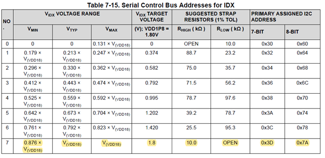
5. Change I2C bus and address in function "Board_fpdU954GetI2CAddr"
void Board_fpdU954GetI2CAddr(uint8_t *chNum,
                             uint8_t *i2cAddr,
                             uint32_t csiInst)
{
    //J7_TODO: Need to update to make it generic across the devices and platforms
    if (csiInst == BOARD_CSI_INST_0)
    {
        *chNum = 2U;
        // *i2cAddr = 0x3DU;   /* 7-bits mode address */
        *i2cAddr = 0x7AU;   /* 8-bits mode address */
    }
    else if (csiInst == BOARD_CSI_INST_1)
    {
        *chNum = 0U;
        // *i2cAddr = 0x30U;   /* 7-bits mode address */
        *i2cAddr = 0x60U;   /* 8-bits mode address */
    }
    else
    {
        *chNum = 0U;
        *i2cAddr = 0U;
    }
}
Our Board Using address as below: