


Part Number: DRA829V
Other Parts Discussed in Thread: DRA829, AM5706
Hi team,
My customer is designing a PCB with secure boot that implements the DRA829 High-Security device and supports OTP eFuse programming.
This question is to confirm the circuit that should be implemented as hardware.
Please refer to the following for the circuit diagram image.
They would like to confirm whether it is enough or not. Please let me know what features are missing.
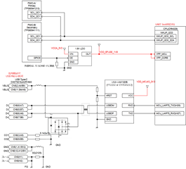
Explanation:
1. It must be possible to boot from MCU_UART0 or WKUP_UART0 with the pin setting of "UART Primary Boot Mode" or "UART Backup Boot Mode".
At that time, a UART-USB conversion circuit is required in consideration of connecting to a personal computer.
2. Prepare a 1.8V LDO that can be controlled ON/OFF by GPIO9 of TPS65941111-Q1 as the power supply for VPP_CORE and VPP_MCU of DRA829.
They have also adopted the AM5706, what do you think of this ?
Thank you in advance.
Best Regards,
Kenley
