Part Number: TDA4VM
Hi experts
Problem Description:
GPIO cannot be controlled on C66x DSP, and can be controlled successfully on R5 and C7x with the same code
Operation method:
1. Board: SK-TDA4VM, SDK version: ti-processor-sdk-rtos-j721e-evm-08_06_01_03
2. Using the PDK inside the SDK, add the GPIO test program on the basis of ipc_echo_test_freertos (modified from pdk_jacinto_08_06_01_03\packages\ti\drv\gpio\test\led_blink\src\main_led_blink.c), see attachment
Board_initGPIO();
GPIO_init();
while(1)
{
GPIO_toggle(USER_LED0);
Osal_delay(500);
3. Modify pinmux, see attachment
{
PIN_PRG0_PRU1_GPO1, PIN_MODE(7) | \
((PIN_PULL_DISABLE) & (~PIN_PULL_DIRECTION | ~PIN_INPUT_ENABLE))
},
4. Compile pdk_lib and ipc_echo_test_freertos to C66X respectively,
make -s pdk_libs BOARD=j721e_evm CORE=c66xdsp_1
make -s ipc_echo_test_freertos BOARD=j721e_evm CORE=c66xdsp_1
5. Use CCS to load the compiled product into the development board and run it
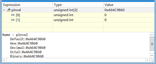
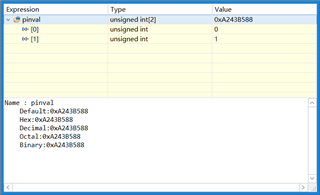
6. The LED on the development board cannot be turned on, and the LED corresponds to GPIO0_16 AD28
If compiled for C7x or R5F, the LED can be lit successfully
make -s pdk_libs BOARD=j721e_evm CORE=mcu1_0
make -s pdk_libs BOARD=j721e_evm CORE=c7x_1
make -s ipc_echo_test_freertos BOARD=j721e_evm CORE=mcu1_0
make -s ipc_echo_test_freertos BOARD=j721e_evm CORE=c7x_1
/*
 *  Copyright (c) Texas Instruments Incorporated 2018
 *  All rights reserved.
 *
 *  Redistribution and use in source and binary forms, with or without
 *  modification, are permitted provided that the following conditions
 *  are met:
 *
 *    Redistributions of source code must retain the above copyright
 *    notice, this list of conditions and the following disclaimer.
 *
 *    Redistributions in binary form must reproduce the above copyright
 *    notice, this list of conditions and the following disclaimer in the
 *    documentation and/or other materials provided with the
 *    distribution.
 *
 *    Neither the name of Texas Instruments Incorporated nor the names of
 *    its contributors may be used to endorse or promote products derived
 *    from this software without specific prior written permission.
 *
 *  THIS SOFTWARE IS PROVIDED BY THE COPYRIGHT HOLDERS AND CONTRIBUTORS
 *  "AS IS" AND ANY EXPRESS OR IMPLIED WARRANTIES, INCLUDING, BUT NOT
 *  LIMITED TO, THE IMPLIED WARRANTIES OF MERCHANTABILITY AND FITNESS FOR
 *  A PARTICULAR PURPOSE ARE DISCLAIMED. IN NO EVENT SHALL THE COPYRIGHT
 *  OWNER OR CONTRIBUTORS BE LIABLE FOR ANY DIRECT, INDIRECT, INCIDENTAL,
 *  SPECIAL, EXEMPLARY, OR CONSEQUENTIAL DAMAGES (INCLUDING, BUT NOT
 *  LIMITED TO, PROCUREMENT OF SUBSTITUTE GOODS OR SERVICES; LOSS OF USE,
 *  DATA, OR PROFITS; OR BUSINESS INTERRUPTION) HOWEVER CAUSED AND ON ANY
 *  THEORY OF LIABILITY, WHETHER IN CONTRACT, STRICT LIABILITY, OR TORT
 *  (INCLUDING NEGLIGENCE OR OTHERWISE) ARISING IN ANY WAY OUT OF THE USE
 *  OF THIS SOFTWARE, EVEN IF ADVISED OF THE POSSIBILITY OF SUCH DAMAGE.
 */

/**
 *  \file main_tirtos.c
 *
 *  \brief Main file for TI-RTOS build
 */

/* ========================================================================== */
/*                             Include Files                                  */
/* ========================================================================== */

#include <stdio.h>
#include <stdint.h>
#include <string.h>

#include <ti/drv/ipc/examples/common/src/ipc_setup.h>

#include <ti/osal/osal.h>
#include <ti/osal/TaskP.h>

#include "ipc_utils.h"
#include <ti/csl/csl_types.h>
#if defined (BUILD_C7X)
#include <ti/csl/soc.h>
#include <ti/csl/csl_clec.h>
#include <ti/csl/arch/csl_arch.h>

#include <ti/osal/soc/osal_soc.h>

#if (defined (FREERTOS))
#include "Hwi.h"
#include "Mmu.h"
#elif (defined (SAFERTOS))
#include "Mmu.h"
#endif
#endif

#include <ti/drv/sciclient/sciclient.h>
#include <ti/board/board.h>

#if (defined (BUILD_MCU1_0) && (defined (SOC_J721E) || defined (SOC_J7200) || defined (SOC_J721S2) || defined (SOC_J784S4)))
#include <ti/drv/sciclient/src/sciclient/sciclient_priv.h>
#include <ti/drv/sciclient/sciserver_tirtos.h>
#endif

/* This needs to be enabled only for negative test cases */
#ifdef IPC_NEGATIVE_TEST
#include <ti/drv/ipc/examples/rtos/ipc_negative_test/ipc_neg_setup.h>
#endif

/* TI-RTOS Header files */
#include <ti/drv/gpio/GPIO.h>
#include <ti/drv/gpio/soc/GPIO_soc.h>
#include <ti/csl/src/ip/gpio/V0/gpio.h>

// #include "GPIO_log.h"
// #include "GPIO_board.h"

#include <ti/board/board.h>

#include <ti/csl/soc.h>

#if defined (BUILD_C7X)
#include <ti/csl/arch/csl_arch.h>
#endif

// #include "ti/mathlib/mathlib.h"

/* ========================================================================== */
/*                           Macros & Typedefs                                */
/* ========================================================================== */

#define APP_TSK_STACK_MAIN              (32U * 1024U)
/**< Test application stack size */

#if (defined (BUILD_MCU1_0) && (defined (SOC_J721E) || defined (SOC_J7200) || defined (SOC_J721S2) || defined (SOC_J784S4)))
/**< SCI Server Init Task stack size */
#define APP_SCISERVER_INIT_TSK_STACK        (32U * 1024U)
/* SCI Server Init Task Priority - must be higher than High priority Sciserver task */
#define IPC_INIT_SCISERVER_TASK_PRI         (6)
#endif

/* High Priority for SCI Server - must be higher than Low priority task */
#define IPC_SETUP_SCISERVER_TASK_PRI_HIGH   (5)
/*
 * Low Priority for SCI Server - must be higher than IPC echo test tasks
 * to prevent delay in handling Sciserver requests when test is performing
 * multicore ping/pong.
 */
#define IPC_SETUP_SCISERVER_TASK_PRI_LOW    (4)

#define USER_LED0 0
#define GPIO_LED0_PIN_NUM 64
#define GPIO_LED0_PORT_NUM 0

#define USER_LED1 1
#define GPIO_LED1_PIN_NUM 71
#define GPIO_LED1_PORT_NUM 0

/* ========================================================================== */
/*                         Structure Declarations                             */
/* ========================================================================== */

/* None */

/* ========================================================================== */
/*                          Function Declarations                             */
/* ========================================================================== */

static void taskFxn(void* a0, void* a1);

#if (defined (BUILD_MCU1_0) && (defined (SOC_J721E) || defined (SOC_J7200) || defined (SOC_J721S2) || defined (SOC_J784S4)))
void Ipc_setupSciServer(void *arg0, void *arg1);
/**< Initialize SCI Server, to process RM/PM Requests by other cores */
#endif

/* ========================================================================== */
/*                            Global Variables                                */
/* ========================================================================== */

/* Test application stack */
/* For SafeRTOS on R5F with FFI Support, task stack should be aligned to the stack size */
#if defined(SAFERTOS) && defined (BUILD_MCU)
static uint8_t  gAppTskStackMain[APP_TSK_STACK_MAIN]
__attribute__ ((aligned(APP_TSK_STACK_MAIN)));
#else
static uint8_t  gAppTskStackMain[APP_TSK_STACK_MAIN]
__attribute__ ((aligned(8192)));
#endif

/* Variable to check if ipc_boardInit has completed or not*/
uint8_t  gBoardinit=0;

#if (defined (BUILD_MCU1_0) && (defined (SOC_J721E) || defined (SOC_J7200) || defined (SOC_J721S2) || defined (SOC_J784S4)))
/* Sciserver Init TAsk stack */
#if defined(SAFERTOS)
static uint8_t  gSciserverInitTskStack[APP_SCISERVER_INIT_TSK_STACK]
__attribute__ ((aligned(APP_SCISERVER_INIT_TSK_STACK)));
#else
static uint8_t  gSciserverInitTskStack[APP_SCISERVER_INIT_TSK_STACK]
__attribute__ ((aligned(8192)));
#endif
extern Sciclient_ServiceHandle_t gSciclientHandle;
#endif

/* ========================================================================== */
/*                          Function Definitions                              */
/* ========================================================================== */


void ipc_initSciclient()
{
    int32_t ret = CSL_PASS;
    Sciclient_ConfigPrms_t        config;

    /* Now reinitialize it as default parameter */
    ret = Sciclient_configPrmsInit(&config);
    if (ret != CSL_PASS)
    {
        App_printf("Sciclient_configPrmsInit Failed\n");
    }

#if (defined (BUILD_MCU1_0) && (defined (SOC_J721E) || defined (SOC_J7200) || defined (SOC_J721S2) || defined (SOC_J784S4)))
    if (ret == CSL_PASS)
    {
        ret = Sciclient_boardCfgParseHeader(
            (uint8_t *)SCISERVER_COMMON_X509_HEADER_ADDR,
            &config.inPmPrms, &config.inRmPrms);
        if (ret != CSL_PASS)
        {
            App_printf("Sciclient_boardCfgParseHeader Failed\n");
        }
    }
#endif

    if (ret == CSL_PASS)
    {
        ret = Sciclient_init(&config);
        if (ret != CSL_PASS)
        {
            App_printf("Sciclient_init Failed\n");
        }
#if (defined (BUILD_MCU1_0) && (defined (SOC_J721E) || defined (SOC_J7200) || defined (SOC_J721S2) || defined (SOC_J784S4)))
        if (gSciclientHandle.rmBoardConfigComplete == SCICLIENT_FT_PASS)
        {
            App_printf("Sciclient_boardCfgRm init Passed\n");
        }
        else
        {
            App_printf("Sciclient_boardCfgRm init FAILED!\n");
        }
#endif
    }
}

void ipc_boardInit()
{
    Board_initCfg           boardCfg;

    boardCfg = BOARD_INIT_UART_STDIO;
#if defined(A72_LINUX_OS)
    /* Configure UART TX pinmux only. Linux doesn't support full pinmux config */
    Board_uartTxPinmuxConfig();
#else
    boardCfg |= BOARD_INIT_PINMUX_CONFIG;
#endif

    Board_init(boardCfg);

    /* Mark Board_init() has been called */
    gBoardinit = 1;
}

/* GPIO Driver board specific pin configuration structure */
GPIO_PinConfig gpioPinConfigs[] =
{
    /* Input pin with interrupt enabled */
    GPIO_DEVICE_CONFIG(GPIO_LED0_PORT_NUM, GPIO_LED0_PIN_NUM) |
    GPIO_CFG_OUTPUT,

    /* Output pin */
    GPIO_DEVICE_CONFIG(GPIO_LED1_PORT_NUM, GPIO_LED1_PIN_NUM) |
    GPIO_CFG_OUTPUT,
};

/* GPIO Driver call back functions */
GPIO_CallbackFxn gpioCallbackFunctions[] =
{
    NULL,
    NULL
};

/* GPIO Driver configuration structure */
GPIO_v0_Config GPIO_v0_config =
{
    gpioPinConfigs,
    gpioCallbackFunctions,
    sizeof(gpioPinConfigs) / sizeof(GPIO_PinConfig),
    sizeof(gpioCallbackFunctions) / sizeof(GPIO_CallbackFxn),
#if (__ARM_ARCH == 7) && (__ARM_ARCH_PROFILE == 'R') /* R5F */
    0x8U
#else
#if defined(BUILD_C7X) || defined(BUILD_C66X)
    0x01U
#else
    0x20U
#endif
#endif
};

/* Callback function */
void AppGpioCallbackFxn(void);


/* Main domain GPIO interrupt events */
#define MAIN_GPIO_INTRTR_GPIO0_BANK0_INT (0x000000C0) /* GPIO port 0 bank 0 interrupt event #, input to MAIN_GPIO_INTRTR */
#define MAIN_GPIO_INTRTR_GPIO1_BANK0_INT (0x000000C8) /* GPIO port 1 bank 0 interrupt event #, input to MAIN_GPIO_INTRTR */

/* Main domain GPIO interrupt events */
#define WKUP_GPIO_INTRTR_GPIO0_BANK0_INT (0x0000003C) /* GPIO port 0 bank 0 interrupt event #, input to WKUP_GPIO_INTRTR */


/* Main to MCU GPIO interrupt router mux output events */
#define CSL_MAIN2MCU_INTRTR_PLS_GPIOMUX_INT0_DFLT_PLS  (0x00000000)
#define CSL_MAIN2MCU_INTRTR_PLS_GPIOMUX_INT31_DFLT_PLS (0x0000001F)

void GPIO_configIntRouter(uint32_t portNum, uint32_t pinNum, uint32_t gpioIntRtrOutIntNum, GPIO_v0_HwAttrs *cfg)
{
    GPIO_IntCfg       *intCfg;

    intCfg = cfg->intCfg;

    /* Use main domain GPIO pins directly connected to IDK EVM */

    intCfg[pinNum].eventId = 0;
    intCfg[pinNum].intcMuxNum = INVALID_INTC_MUX_NUM;
    intCfg[pinNum].intcMuxInEvent = 0;
    intCfg[pinNum].intcMuxOutEvent = 0;


    /* no main domain GPIO pins directly connected to LEDs on GP EVM,
       use WKUP domain GPIO pins which connected to LEDs on base board */
    cfg->baseAddr = CSL_GPIO0_BASE;

    // GPIO_log("\nIntConfig:  portNum[%d], pinNum[%d], bankNum[%d], intNum[%d], eventId[%d]", portNum, pinNum,bankNum, intCfg[pinNum].intNum, intCfg[pinNum].eventId);
}
Board_STATUS Board_unlockMMRPartition(uint32_t domain, uint32_t partNum);
static void Board_initGPIO(void)
{
    Board_initCfg boardCfg;

    GPIO_v0_HwAttrs gpio_cfg;

    /* Get the default SPI init configurations */
    GPIO_socGetInitCfg(GPIO_LED0_PORT_NUM, &gpio_cfg);

    boardCfg = BOARD_INIT_PINMUX_CONFIG |
        BOARD_INIT_MODULE_CLOCK |
        BOARD_INIT_UART_STDIO;// | BOARD_INIT_UNLOCK_MMR;

    // Board_unlockMMRPartition(0, 0);
    // Board_unlockMMRPartition(0, 1);
    // Board_unlockMMRPartition(0, 2);
    // Board_unlockMMRPartition(0, 3);
    // Board_unlockMMRPartition(0, 4);
    // Board_unlockMMRPartition(0, 5);
    // Board_unlockMMRPartition(0, 6);
    // Board_unlockMMRPartition(0, 7);

    Board_init(boardCfg);

    /* Modify the default GPIO configurations if necessary */

	/* change default GPIO port from MAIN GPIO0 to WAKEUP GPIO0 to access TP45 */
    gpio_cfg.baseAddr = CSL_GPIO0_BASE;

    // GPIO_configIntRouter(GPIO_LED0_PORT_NUM, GPIO_LED0_PIN_NUM, 0, &gpio_cfg);
    // GPIO_configIntRouter(GPIO_LED0_PORT_NUM, GPIO_LED1_PIN_NUM, 0, &gpio_cfg);

    /* For J721E EVM, there is not GPIO pin directly connected to LEDs */
	/* J7ES: use WAKEUP GPIO0_6 --> TP45 for testing */
    /* Set the default GPIO init configurations */
    GPIO_socSetInitCfg(GPIO_LED0_PORT_NUM, &gpio_cfg);
}

int main(void)
{
    TaskP_Handle task;
    TaskP_Params taskParams;

    // 68EF3490
    // D172BC5A

#if defined ECHO_TEST_BTCM && defined FREERTOS && defined BUILD_MCU
    /* Relocate FreeRTOS Reset Vectors from BTCM*/
    void _freertosresetvectors (void);
    memcpy((void *)0x0, (void *)_freertosresetvectors, 0x40);
#endif

#if defined ECHO_TEST_BTCM && defined SAFERTOS && defined BUILD_MCU
    /* Relocate FreeRTOS Reset Vectors from BTCM*/
    void _safeRTOSrstvectors (void);
    memcpy((void *)0x0, (void *)_safeRTOSrstvectors, 0x40);
#endif

    /*  This should be called before any other OS calls (like Task creation, OS_start, etc..) */
    OS_init();

    /* Initialize the task params */
    TaskP_Params_init(&taskParams);
    /* Set the task priority higher than the default priority (1) */
    taskParams.priority = 2;
    taskParams.stack        = gAppTskStackMain;
    taskParams.stacksize    = sizeof (gAppTskStackMain);

    // taskFxn(NULL, NULL);

    task = TaskP_create(&taskFxn, &taskParams);
    if(NULL == task)
    {
        OS_stop();
    }
    OS_start();    /* does not return */

    return(0);
}

static void taskFxn(void* a0, void* a1)
{

    /* Initialize SCI Client - It must be called before board init */
    ipc_initSciclient();
    /* IPC Board Init should be done only for MCU1_0 for Linux,
     * unconditionally for RTOS
     */
#if defined(A72_LINUX_OS) && defined(BUILD_MCU1_0)
    ipc_boardInit();
#elif !defined(A72_LINUX_OS)
    ipc_boardInit();
#endif

#if (defined (BUILD_MCU1_0) && (defined (SOC_J721E) || defined (SOC_J7200) || defined (SOC_J721S2) || defined (SOC_J784S4)))
    TaskP_Handle sciserverInitTask;
    TaskP_Params sciserverInitTaskParams;

    /* Initialize SCI Client Server */
    TaskP_Params_init(&sciserverInitTaskParams);
    sciserverInitTaskParams.priority     = IPC_INIT_SCISERVER_TASK_PRI;
    sciserverInitTaskParams.stack        = gSciserverInitTskStack;
    sciserverInitTaskParams.stacksize    = sizeof (gSciserverInitTskStack);

    sciserverInitTask = TaskP_create(&Ipc_setupSciServer, &sciserverInitTaskParams);
    if(NULL == sciserverInitTask)
    {
        OS_stop();
    }
#endif

#if defined (_TMS320C6X)
#if defined (FREERTOS) || defined (SAFERTOS)
    ipc_cacheMarInit();
#endif
#endif

    Board_initGPIO();

    GPIO_init();

    while(1)
    {
        GPIO_toggle(USER_LED0);
        Osal_delay(500);

        // GPIO_write(USER_LED0, 0);
        // Osal_delay(500);

        // GPIO_write(USER_LED0, 1);
        // Osal_delay(500);

    }

// #ifdef IPC_NEGATIVE_TEST
//     Ipc_echo_neg_test();
// #else
//     Ipc_echo_test();
// #endif
}

void setGPIO()
{
    GPIO_write(USER_LED1, 1);
}

void clrGPIO()
{
    GPIO_write(USER_LED1, 0);
}

#if defined(BUILD_C7X)
void InitMmu(void)
{
    IpcInitMmu(FALSE);
    IpcInitMmu(TRUE);
    OsalCfgClecAccessCtrl(false);

}
#endif

#if defined(BUILD_MPU)
extern void Osal_initMmuDefault(void);
void InitMmu(void)
{
    Osal_initMmuDefault();
}
#endif

#if (defined (BUILD_MCU1_0) && (defined (SOC_J721E) || defined (SOC_J7200) || defined (SOC_J721S2) || defined (SOC_J784S4)))
void Ipc_setupSciServer(void *arg0, void *arg1)
{

    Sciserver_TirtosCfgPrms_t appPrms;
    int32_t ret = CSL_PASS;
    char *version_str = NULL;
    char *rmpmhal_version_str = NULL;

    ret = Sciserver_tirtosInitPrms_Init(&appPrms);

    appPrms.taskPriority[SCISERVER_TASK_USER_LO] =
                                            IPC_SETUP_SCISERVER_TASK_PRI_LOW;
    appPrms.taskPriority[SCISERVER_TASK_USER_HI] =
                                            IPC_SETUP_SCISERVER_TASK_PRI_HIGH;

    if (ret == CSL_PASS)
    {
        ret = Sciserver_tirtosInit(&appPrms);
    }

    version_str = Sciserver_getVersionStr();
    rmpmhal_version_str = Sciserver_getRmPmHalVersionStr();
    App_printf("DM Built On: %s %s\n", __DATE__, __TIME__);
    App_printf("Sciserver Version: %s\n", version_str);
    App_printf("RM_PM_HAL Version: %s\n", rmpmhal_version_str);

    if (ret == CSL_PASS)
    {
        App_printf("Starting Sciserver..... PASSED\n");
    }
    else
    {
        App_printf("Starting Sciserver..... FAILED\n");
    }

    return;
}
#endif
/**
* Note: This file was auto-generated by TI PinMux on 5/26/2019 at 3:24:31 PM.
*
* \file  J721E_pinmux_data.c
*
* \brief  This file contains the pin mux configurations for the boards.
*         These are prepared based on how the peripherals are extended on
*         the boards.
*
* \copyright Copyright (CU) 2019 Texas Instruments Incorporated -
*             http://www.ti.com/
*/

/* ========================================================================== */
/*                             Include Files                                  */
/* ========================================================================== */

#include "J721E_pinmux.h"

/** Peripheral Pin Configurations */


static pinmuxPerCfg_t gGpio0PinCfg[] =
{
    /* MyGPIO0 -> GPIO0_11 -> AD21 */
    {
        PIN_PRG1_PRU0_GPO10, PIN_MODE(7) | \
        ((PIN_PULL_DISABLE | PIN_INPUT_ENABLE) & (~PIN_PULL_DIRECTION))
    },
    /* MyGPIO0 -> GPIO0_45 -> AE27 */
    {
        PIN_PRG0_PRU0_GPO2, PIN_MODE(7) | \
        ((PIN_PULL_DISABLE | PIN_INPUT_ENABLE) & (~PIN_PULL_DIRECTION))
    },
    /* MyGPIO0 -> GPIO0_46 -> AD26 */
    {
        PIN_PRG0_PRU0_GPO3, PIN_MODE(7) | \
        ((PIN_PULL_DISABLE | PIN_INPUT_ENABLE) & (~PIN_PULL_DIRECTION))
    },
    /* MyGPIO0 -> GPIO0_65 -> AD27 */
    {
        PIN_PRG0_PRU1_GPO2, PIN_MODE(7) | \
        ((PIN_PULL_DISABLE | PIN_INPUT_ENABLE) & (~PIN_PULL_DIRECTION))
    },
    /* MyGPIO0 -> GPIO0_66 -> AC25 */
    {
        PIN_PRG0_PRU1_GPO3, PIN_MODE(7) | \
        ((PIN_PULL_DISABLE | PIN_INPUT_ENABLE) & (~PIN_PULL_DIRECTION))
    },
    /* MyGPIO0 -> GPIO0_76 -> AF26 */
    {
        PIN_PRG0_PRU1_GPO13, PIN_MODE(7) | \
        ((PIN_PULL_DISABLE | PIN_INPUT_ENABLE) & (~PIN_PULL_DIRECTION))
    },
    /* MyGPIO0 -> GPIO0_78 -> AF29 */
    {
        PIN_PRG0_PRU1_GPO15, PIN_MODE(7) | \
        ((PIN_PULL_DISABLE | PIN_INPUT_ENABLE) & (~PIN_PULL_DIRECTION))
    },
    /* MyGPIO0 -> GPIO0_79 -> AG29 */
    {
        PIN_PRG0_PRU1_GPO16, PIN_MODE(7) | \
        ((PIN_PULL_DISABLE | PIN_INPUT_ENABLE) & (~PIN_PULL_DIRECTION))
    },
    {PINMUX_END}
};

static pinmuxPerCfg_t gGpio1PinCfg[] =
{
    /* MyGPIO1 -> GPIO1_23 -> T28 */
    {
        PIN_MMC2_DAT3, PIN_MODE(7) | \
        ((PIN_PULL_DISABLE | PIN_INPUT_ENABLE) & (~PIN_PULL_DIRECTION))
    },
    /* MyGPIO1 -> GPIO1_24 -> T29 */
    {
        PIN_MMC2_DAT2, PIN_MODE(7) | \
        ((PIN_PULL_DISABLE | PIN_INPUT_ENABLE) & (~PIN_PULL_DIRECTION))
    },
    {PINMUX_END}
};

static pinmuxModuleCfg_t gGpioPinCfg[] =
{
    {0, TRUE, gGpio0PinCfg},
    {1, TRUE, gGpio1PinCfg},
    {PINMUX_END}
};


static pinmuxPerCfg_t gMcasp1PinCfg[] =
{
    /* MyMCASP1 -> MCASP1_ACLKX -> AB27 */
    {
        PIN_PRG0_PRU1_GPO5, PIN_MODE(12) | \
        ((PIN_PULL_DISABLE | PIN_INPUT_ENABLE) & (~PIN_PULL_DIRECTION))
    },
    /* MyMCASP1 -> MCASP1_AFSX -> AA28    0x00011C120 */
    {
        PIN_PRG0_PRU1_GPO8, PIN_MODE(7) | \
        ((PIN_PULL_DISABLE) & (~PIN_PULL_DIRECTION | ~PIN_INPUT_ENABLE))
    },
    /* MyMCASP1 -> MCASP1_AXR0 -> AE29 */
    {
        PIN_PRG0_PRU1_GPO0, PIN_MODE(12) | \
        ((PIN_PULL_DISABLE | PIN_INPUT_ENABLE) & (~PIN_PULL_DIRECTION))
    },
    /* MyMCASP1 -> MCASP1_AXR1 -> AD28    0x00011C104 */
    {
        PIN_PRG0_PRU1_GPO1, PIN_MODE(7) | \
        ((PIN_PULL_DISABLE) & (~PIN_PULL_DIRECTION | ~PIN_INPUT_ENABLE))
    },
    /* MyMCASP1 -> MCASP1_AXR2 -> AD29 */
    {
        PIN_PRG0_PRU1_GPO4, PIN_MODE(12) | \
        ((PIN_PULL_DISABLE | PIN_INPUT_ENABLE) & (~PIN_PULL_DIRECTION))
    },
    /* MyMCASP1 -> MCASP1_AXR3 -> AC26 */
    {
        PIN_PRG0_PRU1_GPO6, PIN_MODE(12) | \
        ((PIN_PULL_DISABLE | PIN_INPUT_ENABLE) & (~PIN_PULL_DIRECTION))
    },
    /* MyMCASP1 -> MCASP1_AXR5 -> Y24 */
    {
        PIN_PRG0_PRU1_GPO9, PIN_MODE(12) | \
        ((PIN_PULL_DISABLE | PIN_INPUT_ENABLE) & (~PIN_PULL_DIRECTION))
    },
    /* MyMCASP1 -> MCASP1_AXR6 -> AA25 */
    {
        PIN_PRG0_PRU1_GPO10, PIN_MODE(12) | \
        ((PIN_PULL_DISABLE | PIN_INPUT_ENABLE) & (~PIN_PULL_DIRECTION))
    },
    /* MyMCASP1 -> MCASP1_AXR7 -> AG26 */
    {
        PIN_PRG0_PRU1_GPO11, PIN_MODE(12) | \
        ((PIN_PULL_DISABLE | PIN_INPUT_ENABLE) & (~PIN_PULL_DIRECTION))
    },
    /* MyMCASP1 -> MCASP1_AXR8 -> AF27 */
    {
        PIN_PRG0_PRU1_GPO12, PIN_MODE(12) | \
        ((PIN_PULL_DISABLE | PIN_INPUT_ENABLE) & (~PIN_PULL_DIRECTION))
    },
    {PINMUX_END}
};

static pinmuxPerCfg_t gMcasp0PinCfg[] =
{
    /* MyMCASP0 -> MCASP0_ACLKX -> AB26 */
    {
        PIN_PRG0_PRU0_GPO9, PIN_MODE(12) | \
        ((PIN_PULL_DISABLE | PIN_INPUT_ENABLE) & (~PIN_PULL_DIRECTION))
    },
    /* MyMCASP0 -> MCASP0_AFSX -> AB25 */
    {
        PIN_PRG0_PRU0_GPO10, PIN_MODE(12) | \
        ((PIN_PULL_DISABLE | PIN_INPUT_ENABLE) & (~PIN_PULL_DIRECTION))
    },
    /* MyMCASP0 -> MCASP0_AXR0 -> AF28 */
    {
        PIN_PRG0_PRU0_GPO0, PIN_MODE(12) | \
        ((PIN_PULL_DISABLE | PIN_INPUT_ENABLE) & (~PIN_PULL_DIRECTION))
    },
    /* MyMCASP0 -> MCASP0_AXR1 -> AE28 */
    {
        PIN_PRG0_PRU0_GPO1, PIN_MODE(12) | \
        ((PIN_PULL_DISABLE | PIN_INPUT_ENABLE) & (~PIN_PULL_DIRECTION))
    },
    /* MyMCASP0 -> MCASP0_AXR10 -> AG28 */
    {
        PIN_PRG0_PRU0_GPO14, PIN_MODE(12) | \
        ((PIN_PULL_DISABLE | PIN_INPUT_ENABLE) & (~PIN_PULL_DIRECTION))
    },
    /* MyMCASP0 -> MCASP0_AXR11 -> AG27 */
    {
        PIN_PRG0_PRU0_GPO15, PIN_MODE(12) | \
        ((PIN_PULL_DISABLE | PIN_INPUT_ENABLE) & (~PIN_PULL_DIRECTION))
    },
    /* MyMCASP0 -> MCASP0_AXR12 -> AH28 */
    {
        PIN_PRG0_PRU0_GPO16, PIN_MODE(12) | \
        ((PIN_PULL_DISABLE | PIN_INPUT_ENABLE) & (~PIN_PULL_DIRECTION))
    },
    /* MyMCASP0 -> MCASP0_AXR13 -> AB24 */
    {
        PIN_PRG0_PRU0_GPO17, PIN_MODE(12) | \
        ((PIN_PULL_DISABLE | PIN_INPUT_ENABLE) & (~PIN_PULL_DIRECTION))
    },
    /* MyMCASP0 -> MCASP0_AXR2 -> AD25 */
    {
        PIN_PRG0_PRU0_GPO4, PIN_MODE(12) | \
        ((PIN_PULL_DISABLE | PIN_INPUT_ENABLE) & (~PIN_PULL_DIRECTION))
    },
    /* MyMCASP0 -> MCASP0_AXR3 -> AC29 */
    {
        PIN_PRG0_PRU0_GPO5, PIN_MODE(12) | \
        ((PIN_PULL_DISABLE | PIN_INPUT_ENABLE) & (~PIN_PULL_DIRECTION))
    },
    /* MyMCASP0 -> MCASP0_AXR4 -> AE26 */
    {
        PIN_PRG0_PRU0_GPO6, PIN_MODE(12) | \
        ((PIN_PULL_DISABLE | PIN_INPUT_ENABLE) & (~PIN_PULL_DIRECTION))
    },
    /* MyMCASP0 -> MCASP0_AXR5 -> AC28 */
    {
        PIN_PRG0_PRU0_GPO7, PIN_MODE(12) | \
        ((PIN_PULL_DISABLE | PIN_INPUT_ENABLE) & (~PIN_PULL_DIRECTION))
    },
    /* MyMCASP0 -> MCASP0_AXR6 -> AC27 */
    {
        PIN_PRG0_PRU0_GPO8, PIN_MODE(12) | \
        ((PIN_PULL_DISABLE | PIN_INPUT_ENABLE) & (~PIN_PULL_DIRECTION))
    },
    /* MyMCASP0 -> MCASP0_AXR7 -> AJ28 */
    {
        PIN_PRG0_PRU0_GPO11, PIN_MODE(12) | \
        ((PIN_PULL_DISABLE | PIN_INPUT_ENABLE) & (~PIN_PULL_DIRECTION))
    },
    /* MyMCASP0 -> MCASP0_AXR8 -> AH27 */
    {
        PIN_PRG0_PRU0_GPO12, PIN_MODE(12) | \
        ((PIN_PULL_DISABLE | PIN_INPUT_ENABLE) & (~PIN_PULL_DIRECTION))
    },
    /* MyMCASP0 -> MCASP0_AXR9 -> AH29 */
    {
        PIN_PRG0_PRU0_GPO13, PIN_MODE(12) | \
        ((PIN_PULL_DISABLE | PIN_INPUT_ENABLE) & (~PIN_PULL_DIRECTION))
    },
    /* MyMCASP0 -> AUDIO_EXT_REFCLK0 -> AD22 */
    {
        PIN_PRG1_PRU0_GPO6, PIN_MODE(6) | \
        ((PIN_PULL_DISABLE | PIN_INPUT_ENABLE) & (~PIN_PULL_DIRECTION))
    },
    {PINMUX_END}
};

static pinmuxPerCfg_t gMcasp2PinCfg[] =
{
    /* MyMCASP2 -> MCASP2_AXR0 -> AE25 */
    {
        PIN_PRG0_PRU1_GPO14, PIN_MODE(12) | \
        ((PIN_PULL_DISABLE | PIN_INPUT_ENABLE) & (~PIN_PULL_DIRECTION))
    },
    {PINMUX_END}
};

static pinmuxPerCfg_t gMcasp6PinCfg[] =
{
    /* MyMCASP6 -> MCASP6_ACLKR -> AH23 */
    {
        PIN_PRG1_PRU0_GPO4, PIN_MODE(13) | \
        ((PIN_PULL_DISABLE | PIN_INPUT_ENABLE) & (~PIN_PULL_DIRECTION))
    },
    /* MyMCASP6 -> MCASP6_ACLKX -> AC23 */
    {
        PIN_PRG1_PRU0_GPO0, PIN_MODE(12) | \
        ((PIN_PULL_DISABLE | PIN_INPUT_ENABLE) & (~PIN_PULL_DIRECTION))
    },
    /* MyMCASP6 -> MCASP6_AFSX -> AG22 */
    {
        PIN_PRG1_PRU0_GPO1, PIN_MODE(12) | \
        ((PIN_PULL_DISABLE | PIN_INPUT_ENABLE) & (~PIN_PULL_DIRECTION))
    },
    /* MyMCASP6 -> MCASP6_AXR0 -> AF22 */
    {
        PIN_PRG1_PRU0_GPO2, PIN_MODE(12) | \
        ((PIN_PULL_DISABLE | PIN_INPUT_ENABLE) & (~PIN_PULL_DIRECTION))
    },
    /* MyMCASP6 -> MCASP6_AXR1 -> AJ23 */
    {
        PIN_PRG1_PRU0_GPO3, PIN_MODE(12) | \
        ((PIN_PULL_DISABLE | PIN_INPUT_ENABLE) & (~PIN_PULL_DIRECTION))
    },
    /* MyMCASP6 -> AUDIO_EXT_REFCLK1 -> AE20 */
    {
        PIN_PRG1_PRU0_GPO7, PIN_MODE(5) | \
        ((PIN_PULL_DISABLE | PIN_INPUT_ENABLE) & (~PIN_PULL_DIRECTION))
    },
    {PINMUX_END}
};

static pinmuxModuleCfg_t gMcaspPinCfg[] =
{
    {1, TRUE, gMcasp1PinCfg},
    {0, TRUE, gMcasp0PinCfg},
    {2, TRUE, gMcasp2PinCfg},
    {6, TRUE, gMcasp6PinCfg},
    {PINMUX_END}
};


static pinmuxPerCfg_t gSpi3PinCfg[] =
{
    /* MySPI3 -> SPI3_CLK -> Y25 */
    {
        PIN_PRG0_PRU1_GPO17, PIN_MODE(4) | \
        ((PIN_PULL_DISABLE | PIN_INPUT_ENABLE) & (~PIN_PULL_DIRECTION))
    },
    /* MySPI3 -> SPI3_CS0 -> AA24 */
    {
        PIN_PRG0_PRU1_GPO7, PIN_MODE(4) | \
        ((PIN_PULL_DISABLE | PIN_INPUT_ENABLE) & (~PIN_PULL_DIRECTION))
    },
    /* MySPI3 -> SPI3_D0 -> AA26 */
    {
        PIN_PRG0_PRU1_GPO18, PIN_MODE(4) | \
        ((PIN_PULL_DISABLE | PIN_INPUT_ENABLE) & (~PIN_PULL_DIRECTION))
    },
    /* MySPI3 -> SPI3_D1 -> AA29 */
    {
        PIN_PRG0_PRU1_GPO19, PIN_MODE(4) | \
        ((PIN_PULL_DISABLE | PIN_INPUT_ENABLE) & (~PIN_PULL_DIRECTION))
    },
    {PINMUX_END}
};

static pinmuxModuleCfg_t gSpiPinCfg[] =
{
    {3, TRUE, gSpi3PinCfg},
    {PINMUX_END}
};


static pinmuxPerCfg_t gVout0PinCfg[] =
{
    /* MyVOUT1 -> VOUT0_DATA0 -> AE22 */
    {
        PIN_PRG1_PRU1_GPO0, PIN_MODE(10) | \
        ((PIN_PULL_DISABLE) & (~PIN_PULL_DIRECTION & ~PIN_INPUT_ENABLE))
    },
    /* MyVOUT1 -> VOUT0_DATA1 -> AG23 */
    {
        PIN_PRG1_PRU1_GPO1, PIN_MODE(10) | \
        ((PIN_PULL_DISABLE) & (~PIN_PULL_DIRECTION & ~PIN_INPUT_ENABLE))
    },
    /* MyVOUT1 -> VOUT0_DATA2 -> AF23 */
    {
        PIN_PRG1_PRU1_GPO2, PIN_MODE(10) | \
        ((PIN_PULL_DISABLE) & (~PIN_PULL_DIRECTION & ~PIN_INPUT_ENABLE))
    },
    /* MyVOUT1 -> VOUT0_DATA3 -> AD23 */
    {
        PIN_PRG1_PRU1_GPO3, PIN_MODE(10) | \
        ((PIN_PULL_DISABLE) & (~PIN_PULL_DIRECTION & ~PIN_INPUT_ENABLE))
    },
    /* MyVOUT1 -> VOUT0_DATA4 -> AH24 */
    {
        PIN_PRG1_PRU1_GPO4, PIN_MODE(10) | \
        ((PIN_PULL_DISABLE) & (~PIN_PULL_DIRECTION & ~PIN_INPUT_ENABLE))
    },
    /* MyVOUT1 -> VOUT0_DATA5 -> AG21 */
    {
        PIN_PRG1_PRU1_GPO5, PIN_MODE(10) | \
        ((PIN_PULL_DISABLE) & (~PIN_PULL_DIRECTION & ~PIN_INPUT_ENABLE))
    },
    /* MyVOUT1 -> VOUT0_DATA6 -> AE23 */
    {
        PIN_PRG1_PRU1_GPO6, PIN_MODE(10) | \
        ((PIN_PULL_DISABLE) & (~PIN_PULL_DIRECTION & ~PIN_INPUT_ENABLE))
    },
    /* MyVOUT1 -> VOUT0_DATA7 -> AC21 */
    {
        PIN_PRG1_PRU1_GPO7, PIN_MODE(10) | \
        ((PIN_PULL_DISABLE) & (~PIN_PULL_DIRECTION & ~PIN_INPUT_ENABLE))
    },
    /* MyVOUT1 -> VOUT0_DATA8 -> Y23 */
    {
        PIN_PRG1_PRU1_GPO8, PIN_MODE(10) | \
        ((PIN_PULL_DISABLE) & (~PIN_PULL_DIRECTION & ~PIN_INPUT_ENABLE))
    },
    /* MyVOUT1 -> VOUT0_DATA9 -> AF21 */
    {
        PIN_PRG1_PRU1_GPO9, PIN_MODE(10) | \
        ((PIN_PULL_DISABLE) & (~PIN_PULL_DIRECTION & ~PIN_INPUT_ENABLE))
    },
    /* MyVOUT1 -> VOUT0_DATA10 -> AB23 */
    {
        PIN_PRG1_PRU1_GPO10, PIN_MODE(10) | \
        ((PIN_PULL_DISABLE) & (~PIN_PULL_DIRECTION & ~PIN_INPUT_ENABLE))
    },
    /* MyVOUT1 -> VOUT0_DATA11 -> AJ25 */
    {
        PIN_PRG1_PRU1_GPO11, PIN_MODE(10) | \
        ((PIN_PULL_DISABLE) & (~PIN_PULL_DIRECTION & ~PIN_INPUT_ENABLE))
    },
    /* MyVOUT1 -> VOUT0_DATA12 -> AH25 */
    {
        PIN_PRG1_PRU1_GPO12, PIN_MODE(10) | \
        ((PIN_PULL_DISABLE) & (~PIN_PULL_DIRECTION & ~PIN_INPUT_ENABLE))
    },
    /* MyVOUT1 -> VOUT0_DATA13 -> AG25 */
    {
        PIN_PRG1_PRU1_GPO13, PIN_MODE(10) | \
        ((PIN_PULL_DISABLE) & (~PIN_PULL_DIRECTION & ~PIN_INPUT_ENABLE))
    },
    /* MyVOUT1 -> VOUT0_DATA14 -> AH26 */
    {
        PIN_PRG1_PRU1_GPO14, PIN_MODE(10) | \
        ((PIN_PULL_DISABLE) & (~PIN_PULL_DIRECTION & ~PIN_INPUT_ENABLE))
    },
    /* MyVOUT1 -> VOUT0_DATA15 -> AJ27 */
    {
        PIN_PRG1_PRU1_GPO15, PIN_MODE(10) | \
        ((PIN_PULL_DISABLE) & (~PIN_PULL_DIRECTION & ~PIN_INPUT_ENABLE))
    },
    /* MyVOUT1 -> VOUT0_DATA16 -> AF24 */
    {
        PIN_PRG1_PRU0_GPO11, PIN_MODE(10) | \
        ((PIN_PULL_DISABLE) & (~PIN_PULL_DIRECTION & ~PIN_INPUT_ENABLE))
    },
    /* MyVOUT1 -> VOUT0_DATA17 -> AJ24 */
    {
        PIN_PRG1_PRU0_GPO12, PIN_MODE(10) | \
        ((PIN_PULL_DISABLE) & (~PIN_PULL_DIRECTION & ~PIN_INPUT_ENABLE))
    },
    /* MyVOUT1 -> VOUT0_DATA18 -> AG24 */
    {
        PIN_PRG1_PRU0_GPO13, PIN_MODE(10) | \
        ((PIN_PULL_DISABLE) & (~PIN_PULL_DIRECTION & ~PIN_INPUT_ENABLE))
    },
    /* MyVOUT1 -> VOUT0_DATA19 -> AD24 */
    {
        PIN_PRG1_PRU0_GPO14, PIN_MODE(10) | \
        ((PIN_PULL_DISABLE) & (~PIN_PULL_DIRECTION & ~PIN_INPUT_ENABLE))
    },
    /* MyVOUT1 -> VOUT0_DATA20 -> AC24 */
    {
        PIN_PRG1_PRU0_GPO15, PIN_MODE(10) | \
        ((PIN_PULL_DISABLE) & (~PIN_PULL_DIRECTION & ~PIN_INPUT_ENABLE))
    },
    /* MyVOUT1 -> VOUT0_DATA21 -> AE24 */
    {
        PIN_PRG1_PRU0_GPO16, PIN_MODE(10) | \
        ((PIN_PULL_DISABLE) & (~PIN_PULL_DIRECTION & ~PIN_INPUT_ENABLE))
    },
    /* MyVOUT1 -> VOUT0_DATA22 -> AJ20 */
    {
        PIN_PRG1_PRU0_GPO8, PIN_MODE(10) | \
        ((PIN_PULL_DISABLE) & (~PIN_PULL_DIRECTION & ~PIN_INPUT_ENABLE))
    },
    /* MyVOUT1 -> VOUT0_DATA23 -> AG20 */
    {
        PIN_PRG1_PRU0_GPO9, PIN_MODE(10) | \
        ((PIN_PULL_DISABLE) & (~PIN_PULL_DIRECTION & ~PIN_INPUT_ENABLE))
    },
    /* MyVOUT1 -> VOUT0_DE -> AC22 */
    {
        PIN_PRG1_PRU1_GPO17, PIN_MODE(10) | \
        ((PIN_PULL_DISABLE) & (~PIN_PULL_DIRECTION & ~PIN_INPUT_ENABLE))
    },
    /* MyVOUT1 -> VOUT0_EXTPCLKIN -> AH21 */
    {
        PIN_PRG1_PRU0_GPO19, PIN_MODE(10) | \
        ((PIN_PULL_DISABLE | PIN_INPUT_ENABLE) & (~PIN_PULL_DIRECTION))
    },
    /* MyVOUT1 -> VOUT0_HSYNC -> AJ26 */
    {
        PIN_PRG1_PRU1_GPO16, PIN_MODE(10) | \
        ((PIN_PULL_DISABLE) & (~PIN_PULL_DIRECTION & ~PIN_INPUT_ENABLE))
    },
    /* MyVOUT1 -> VOUT0_PCLK -> AH22 */
    {
        PIN_PRG1_PRU1_GPO19, PIN_MODE(10) | \
        ((PIN_PULL_DISABLE) & (~PIN_PULL_DIRECTION & ~PIN_INPUT_ENABLE))
    },
    /* MyVOUT1 -> VOUT0_VSYNC -> AJ22 */
    {
        PIN_PRG1_PRU1_GPO18, PIN_MODE(10) | \
        ((PIN_PULL_DISABLE) & (~PIN_PULL_DIRECTION & ~PIN_INPUT_ENABLE))
    },
    {PINMUX_END}
};

static pinmuxModuleCfg_t gVoutPinCfg[] =
{
    {0, TRUE, gVout0PinCfg},
    {PINMUX_END}
};


static pinmuxPerCfg_t gVpfe0PinCfg[] =
{
    /* MyVPFE1 -> VPFE0_DATA6 -> AJ21 */
    {
        PIN_PRG1_PRU0_GPO17, PIN_MODE(11) | \
        ((PIN_PULL_DISABLE | PIN_INPUT_ENABLE) & (~PIN_PULL_DIRECTION))
    },
    /* MyVPFE1 -> VPFE0_DATA7 -> AE21 */
    {
        PIN_PRG1_PRU0_GPO18, PIN_MODE(11) | \
        ((PIN_PULL_DISABLE | PIN_INPUT_ENABLE) & (~PIN_PULL_DIRECTION))
    },
    /* MyVPFE1 -> VPFE0_DATA11 -> AD19 */
    {
        PIN_PRG1_MDIO0_MDIO, PIN_MODE(11) | \
        ((PIN_PULL_DISABLE | PIN_INPUT_ENABLE) & (~PIN_PULL_DIRECTION))
    },
    /* MyVPFE1 -> VPFE0_DATA12 -> AD18 */
    {
        PIN_PRG1_MDIO0_MDC, PIN_MODE(11) | \
        ((PIN_PULL_DISABLE | PIN_INPUT_ENABLE) & (~PIN_PULL_DIRECTION))
    },
    {PINMUX_END}
};

static pinmuxModuleCfg_t gVpfePinCfg[] =
{
    {0, TRUE, gVpfe0PinCfg},
    {PINMUX_END}
};


pinmuxBoardCfg_t gJ721E_MainPinmuxDataInfo[] =
{
    {0, gGpioPinCfg},
    {1, gMcaspPinCfg},
    {2, gSpiPinCfg},
    {3, gVoutPinCfg},
    {4, gVpfePinCfg},
    {PINMUX_END}
};

pinmuxBoardCfg_t gJ721E_WkupPinmuxDataInfo[] =
{
    {PINMUX_END}
};