This thread has been locked.

If you have a related question, please click the "Ask a related question" button in the top right corner. The newly created question will be automatically linked to this question.

AM3354: eMMC Booting in raw mode in standalone

Part Number: AM3354

Hi,

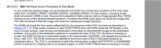
I am trying to boot eMMC in raw mode on my custom board. I tried to load TOC and boot_ti.bin in 0x00 and 0x200 address of eMMC, as mentioned in TRMM of AM335x.

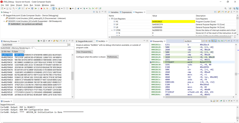
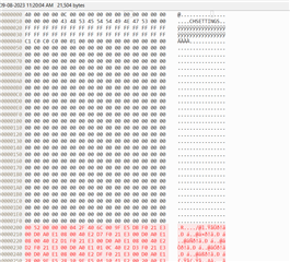
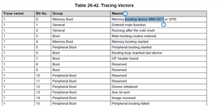
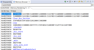
But MPU is only able to detect CHSETTINGS, Not the GP header. I found out by value in tracing vector.

Does the rom will use different code for detecting GP Header. Kindly clarify on the same.

  • When I check with JTAG ROM Code is on the loop at address 0x2862c, TI Team please check on the same.

    Expecting a response as early as possible.

  • Hi,

    As far as I know, we do not debug ROM code. So are you trying to debug SPL?

    What documentation are you following?

    Debug SPL: https://software-dl.ti.com/processor-sdk-linux/esd/AM335X/08_02_00_24/exports/docs/linux/Foundational_Components/U-Boot/Apps-SPL-Debug.html

    Loading u-boot: https://software-dl.ti.com/processor-sdk-linux/esd/AM335X/08_02_00_24/exports/docs/linux/Foundational_Components/U-Boot/Apps-Load-in-CCS.html

    Please provide the above information to better help you.

    ~ Judith

  • Hi Judith,

    Thank you for replying.

    As I am using standalone, I loaded TOC and boot_ti.bin through UART and loaded it into eMMC(Referring to AM335x TRMM).

    I red the data back, I can see the data is correct. 

    I want to know whether micron (MTFC4GLWDM-4M AAT A ) eMMC is compatible with ROM code in RAW mode.

    Because ROM code of eMMC cannot read GP Header which is at 0x200 address of eMMC, But we found that it is able to read CHSETTINGS (In tracing vector CHSETTINGS found bit is set to 1).

    Tracing Vector:

                                    Addr                  :        Value

    Tracing vector 1:     4030CE40h        :      0x0010907F (20th bit of Tracing vector)

    Tracing vector 2:     4030CE44h        :      0x0000F000

    Tracing vector 3:     4030CE48h        :      0x00011000

    I have loaded TOC of 512 bytes at 0x00 address of eMMC as mentioned in AM335x TRMM. And at 0x200 GP header is present, followed by .bin file.

    Why AM335x cannot able to read GP Header, But able to detect CHESTTINGS, Is there any other settings I missed?


  • Hi,

    Discussing this internally and will get back to you.

    ~ Judith

  • Sure, Will be waiting for the response.

  • Hi judith,

    Any update from the team?  Need to rush.

  • Hi Akshata,

    I have discussed this internally and am pending a response. Will ping again and hopefully get a response soon.

    ~ Judith

  • Thank you judith,

    Looking forward for the response soon, since the project is on halt. 

  • Hi Akshata,

    Still pending response, sorry for the delay.

    ~ Judith

  • I have loaded TOC of 512 bytes at 0x00 address of eMMC as mentioned in AM335x TRMM. And at 0x200 GP header is present, followed by .bin file.

    Why AM335x cannot able to read GP Header, But able to detect CHESTTINGS, Is there any other settings I missed?

    If you do a standard build of U-Boot for AM335x the resulting U-Boot SPL file called "MLO" should already contain all the right TOC and GP headers to allow programming the file into an eMMC in RAW mode at offset 0 (or one of the redundant offsets). I just did a quick test build using the ti-u-boot-2023.04 tree, and the resulting start of the MLO file looks as follows:

    a0797059@dasso:~/git/u-boot (ti-u-boot-2023.04)
    $ hexdump -v -C .out_a8/MLO | head -n 40
    00000000  40 00 00 00 0c 00 00 00  00 00 00 00 00 00 00 00  |@...............|
    00000010  00 00 00 00 43 48 53 45  54 54 49 4e 47 53 00 00  |....CHSETTINGS..|
    00000020  ff ff ff ff ff ff ff ff  ff ff ff ff ff ff ff ff  |................|
    00000030  ff ff ff ff ff ff ff ff  ff ff ff ff ff ff ff ff  |................|
    00000040  c1 c0 c0 c0 00 01 00 00  00 00 00 00 00 00 00 00  |................|
    00000050  00 00 00 00 00 00 00 00  00 00 00 00 00 00 00 00  |................|
    00000060  00 00 00 00 00 00 00 00  00 00 00 00 00 00 00 00  |................|
    00000070  00 00 00 00 00 00 00 00  00 00 00 00 00 00 00 00  |................|
    00000080  00 00 00 00 00 00 00 00  00 00 00 00 00 00 00 00  |................|
    00000090  00 00 00 00 00 00 00 00  00 00 00 00 00 00 00 00  |................|
    000000a0  00 00 00 00 00 00 00 00  00 00 00 00 00 00 00 00  |................|
    000000b0  00 00 00 00 00 00 00 00  00 00 00 00 00 00 00 00  |................|
    000000c0  00 00 00 00 00 00 00 00  00 00 00 00 00 00 00 00  |................|
    000000d0  00 00 00 00 00 00 00 00  00 00 00 00 00 00 00 00  |................|
    000000e0  00 00 00 00 00 00 00 00  00 00 00 00 00 00 00 00  |................|
    000000f0  00 00 00 00 00 00 00 00  00 00 00 00 00 00 00 00  |................|
    00000100  00 00 00 00 00 00 00 00  00 00 00 00 00 00 00 00  |................|
    00000110  00 00 00 00 00 00 00 00  00 00 00 00 00 00 00 00  |................|
    00000120  00 00 00 00 00 00 00 00  00 00 00 00 00 00 00 00  |................|
    00000130  00 00 00 00 00 00 00 00  00 00 00 00 00 00 00 00  |................|
    00000140  00 00 00 00 00 00 00 00  00 00 00 00 00 00 00 00  |................|
    00000150  00 00 00 00 00 00 00 00  00 00 00 00 00 00 00 00  |................|
    00000160  00 00 00 00 00 00 00 00  00 00 00 00 00 00 00 00  |................|
    00000170  00 00 00 00 00 00 00 00  00 00 00 00 00 00 00 00  |................|
    00000180  00 00 00 00 00 00 00 00  00 00 00 00 00 00 00 00  |................|
    00000190  00 00 00 00 00 00 00 00  00 00 00 00 00 00 00 00  |................|
    000001a0  00 00 00 00 00 00 00 00  00 00 00 00 00 00 00 00  |................|
    000001b0  00 00 00 00 00 00 00 00  00 00 00 00 00 00 00 00  |................|
    000001c0  00 00 00 00 00 00 00 00  00 00 00 00 00 00 00 00  |................|
    000001d0  00 00 00 00 00 00 00 00  00 00 00 00 00 00 00 00  |................|
    000001e0  00 00 00 00 00 00 00 00  00 00 00 00 00 00 00 00  |................|
    000001f0  00 00 00 00 00 00 00 00  00 00 00 00 00 00 00 00  |................|
    00000200  c0 ae 01 00 00 04 2f 40  0f 00 00 ea 14 f0 9f e5  |....../@........|
    00000210  14 f0 9f e5 14 f0 9f e5  14 f0 9f e5 14 f0 9f e5  |................|
    00000220  14 f0 9f e5 14 f0 9f e5  40 04 2f 40 40 04 2f 40  |........@./@@./@|
    00000230  40 04 2f 40 40 04 2f 40  40 04 2f 40 40 04 2f 40  |@./@@./@@./@@./@|
    00000240  40 04 2f 40 ef be ad de  fe ff ff ea 31 03 00 ea  |@./@........1...|
    00000250  00 00 0f e1 1f 10 00 e2  1a 00 31 e3 1f 00 c0 13  |..........1.....|
    00000260  13 00 80 13 c0 00 80 e3  00 f0 29 e1 10 0f 11 ee  |..........).....|
    00000270  02 0a c0 e3 10 0f 01 ee  98 00 9f e5 10 0f 0c ee  |................|

    You can see the TOC header at offset 0x0, the second TOC being filled with 0xff completely at offset 0x20, then the Magic Values for MMC RAW Mode at offset 0x40, and the GP device header at offset 0x200, designating a boot loader image size of 0x0001aec0 (declared at offset 0x200) and a RAM download address of 0x402f0400 (declared at offset 0x204). The actual boot loader image/code starts at offset 0x208. This all looks like as required by the TRM (note that I've not tried the actual eMMC RAW boot with the image above),

    How does your image look like? Can you compare your hex dump with what is posted above?

    Regards, Andreas

  • Which MMC port are you attempting to boot from?  The tracing vectors indicate you are attempting to boot from MMC0, which is not compatible with larger memories.  Please see section 26.1.8.5.2 of the TRM for more information.

    Regards,

    James

  • Hi Andreas,

    I have compared the TOC, Its same as mentioned by you and in TRMM,

    Below is a file I loaded into eMMC at address 0x00 for your reference.


    Where 0x5200 is file size and 0x402f0400 is start address.

    Is any other configuration missing?

  • Hi James,

    In tracing vector 1 ,BIT 0 is also set which mean it is trying to boot from MMCSD1 or SPI0.  

    MMC0 pins are not connected.

    We have connected eMMC to MMC1 as it is 4GB(MTFC4GLWDM-4M AAT A). 

    SYSBOOT PINS are set to 11100

    so Booting device order: MMC1  >  MMC0  >  UART0  >  USB0

    I have also cross checked the SYSBOOT PINS  in CONTROL_MODULE_STATUS_REGISTER


    LCD_DATA[4:0] = 11100.

    CLARIFICATION: 

    It cannot boot from MMC0 as it is not connected to any SD CARD or eMMC. We have only connected to MMC1 to the pins mentioned in TRMM for booting.

    QUERY: 

    1.How MPU is detecting TOC when MMC0 is not connected? 

    2. Will MPU not move to next booting device after trying to boot previous device( May be leading bit set for MMCSD0 Booting). 

  • Hi James,

    Any update on the queries? Kindly let me know. 

  • Hi Andreas,

    Is there anything also that I have to consider? Kindly let me know. 

  • Hi James,

    I want to know whether ROM code of AM335x is compatible with  4GB(MTFC4GLWDM-4M AAT A) connected to MMC1 in RAW mode, I cant find any forums for booting from eMMC in raw mode.

    Or Is there something that I am missing?

    Any update, Kindly let me know.

  • Hi Andreas,

    Is there a possibility to dump this file and check from your side?

    If yes, then it would be great!

    If so. I would get better understanding ,why it is not working.

    Kindly let me know the result if you can dump and check.

  • Where 0x5200 is file size and 0x402f0400 is start address.

    Is any other configuration missing?

    Why is your initial bootloader only ~21KB in size? How did you build and generate it? When I build the standard "MLO" (which is basically U-Boot SPL, packaged up with some headers and DTB) here locally it is much larger, about ~110KB. Do you have another AM335x board such as as BeagleBone Black where you can try to see if your initial bootloader even works? It will be helpful to isolate where your issue is.

    Regards, Andreas

  • Hi Andreas,

    Thank you for replying.

    We are using custom board(AM3354) with standalone, So we are manually adding TOC to a bootloader.bin file (We have made some changes in bootloader example so the size is reduced to ~21KB)

    I guess there should not be any problem in reading file size of bootloader, Correct me if I am wrong.(Does ROM code needs fixed file size of bootloader.bin in eMMC? If yes, then kindly let me know.)

    Further I have run the bootloader through JTAG, It is running fine(I am able to see UART prints on console). I also cross checked the memory browser, the same .bin is running at address 0x402f0400.

    Expecting a early response. 

    As we cannot proceed until we receive a response here.

  • Ah ok, so you are using some custom bare-metal bootloader.

    We need to narrow down where the issue is, for this I propose:

    1) You build a standard 'MLO' for AM335x, and see if you can get this loaded and running on your board, and

    2) You try programming your custom bootloader into a BeagleBone Black eMMC, and verify if it runs there

    I don't have any access to AM335x hardware at the moment (including of course, your own board), so I'm trying to guide this effort here to enable yourself to resolve the issue.

    If you need guidance regarding (1), of course please let me know,

    Thanks, Andreas

  • Hi Andreas,

    Thank you for the reply.

    I would need help regarding 1.

    As I am using bare-metal, I cannot generate Standard MLO.

    If you could share the generated MLO would be helpful. 

    Or

    Please let me know the steps to generate MLO.

    So that I can dump the same on eMMC and know where the problem is.

  • Please let me know the steps to generate MLO.
    1. Download the current AM335x Linux SDK at https://www.ti.com/tool/PROCESSOR-SDK-AM335X
    2. After installation, an MLO file that is suitable for running on a TI AM335x EVM (including BeagleBone boards, etc.) can be found at board-support/prebuilt-images/MLO-am335x-evm, see here:

      a0797059@dasso:~/ti/ti-processor-sdk-linux-am335x-evm-08.02.00.24
      $ hexdump -C board-support/prebuilt-images/MLO-am335x-evm | head -n 20
      00000000  40 00 00 00 0c 00 00 00  00 00 00 00 00 00 00 00  |@...............|
      00000010  00 00 00 00 43 48 53 45  54 54 49 4e 47 53 00 00  |....CHSETTINGS..|
      00000020  ff ff ff ff ff ff ff ff  ff ff ff ff ff ff ff ff  |................|
      *
      00000040  c1 c0 c0 c0 00 01 00 00  00 00 00 00 00 00 00 00  |................|
      00000050  00 00 00 00 00 00 00 00  00 00 00 00 00 00 00 00  |................|
      *
      00000200  7c aa 01 00 00 04 2f 40  0f 00 00 ea 14 f0 9f e5  ||...../@........|
      00000210  14 f0 9f e5 14 f0 9f e5  14 f0 9f e5 14 f0 9f e5  |................|
      00000220  14 f0 9f e5 14 f0 9f e5  40 04 2f 40 40 04 2f 40  |........@./@@./@|
      00000230  40 04 2f 40 40 04 2f 40  40 04 2f 40 40 04 2f 40  |@./@@./@@./@@./@|
      00000240  40 04 2f 40 ef be ad de  fe ff ff ea 33 00 00 ea  |@./@........3...|
      00000250  00 00 0f e1 1f 10 00 e2  1a 00 31 e3 1f 00 c0 13  |..........1.....|
      00000260  13 00 80 13 c0 00 80 e3  00 f0 29 e1 10 0f 11 ee  |..........).....|
      00000270  02 0a c0 e3 10 0f 01 ee  98 00 9f e5 10 0f 0c ee  |................|
      00000280  06 00 00 eb 22 00 00 eb  16 04 00 eb 15 0f 07 ee  |...."...........|
      00000290  9a 0f 07 ee 95 0f 07 ee  1e ff 2f e1 eb ff ff ea  |........../.....|
      000002a0  00 00 a0 e3 17 0f 08 ee  15 0f 07 ee d5 0f 07 ee  |................|
      000002b0  9a 0f 07 ee 95 0f 07 ee  10 0f 11 ee 02 0a c0 e3  |................|
      000002c0  07 00 c0 e3 02 00 80 e3  02 0b 80 e3 01 0a 80 e3  |................|


    3. If this doesn't generate any UART prints it may be that your board is too different/incompatible from the TI AM335x standard boards. In this case I'd recommend turning on the 'early debug UART' functionality in MLO (== U-Boot SPL) and re-building U-Boot SPL, see https://software-dl.ti.com/processor-sdk-linux/esd/AM335X/08_02_00_24/exports/docs/linux/How_to_Guides/Board_Port/U-Boot.html#u-boot-board-port
      Turning on this functionality will lead to some very early debug prints in the console, long before anything board-specific really is initialized. This is the specific config you'd want to change, taken from the above-referenced documentation:

      CONFIG_DEBUG_UART_BASE=0x44e09000
      CONFIG_DEBUG_UART_CLOCK=48000000
      CONFIG_DEBUG_UART=y
      CONFIG_DEBUG_UART_OMAP=y
      CONFIG_DEBUG_UART_SHIFT=2
      CONFIG_DEBUG_UART_ANNOUNCE=y


      This way, you use such an MLO to see if you get any "signs of life", which would validate your basic boot approach/headers are good (you don't really need to fully port/bring-up U-Boot/SPL for what you do). While this is a "hack" it might just do the trick for what you need. Of course if you use a different UART I/F than the TI default one that would need to be updated accordingly.

    Regards, Andreas

  • Hi Andreas,

    Will try these methods, and update you on the same.