This thread has been locked.

If you have a related question, please click the "Ask a related question" button in the top right corner. The newly created question will be automatically linked to this question.

SK-AM62: Enabling user expansion I/O pins

Part Number: SK-AM62
Other Parts Discussed in Thread: SYSCONFIG

We are using linux 08.06.00.4.2, we need the user expansion I/O pins to be enabled

How can we enable the gpio pins in J3? 

  • Hello Anand,

    I am working on your query.

    You may get a reply in one or two days.

    Regards,

    S.Anill

  • Hello Anand,

    I have looked at some of the GPIO pins from J3 connector , and those are directly connected to the SOC.

    Now, if you want to configure those GPIOs as input or output, you should enable them from CCS If those pins are controlling on R5F and M4F core.

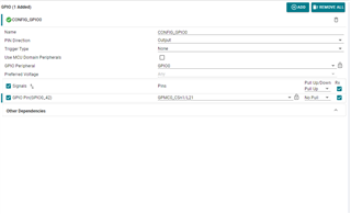
    In the below image, I have configured GPIO0_42 as output and used it in my Application  , which is connected to 13th pin of J3.

    So, you also just follow the same procedure. Simply configure pin mode as per your requirements from CCS and compile and load the binary on your destination core.

    May I know if you are controlling J3 GPIO pins on the A53, R5F, or M4F cores?

    Regards,

    S.Anil.

    Regards,

    S.Anil

  • Now how can I export the GPIO pin.

    I need to select 13 the pin in J3 as input.

    Regards

    Anand

  • Hello Anand,

    Can you please confirm are you trying to configure pin on the A53 or R5F core?

    In R5F, it is very simple, as mentioned above; you just need to configure pin as input only from the system configuration.

    Regards,

    S.Anil.

  • We are using A53

  • we are using sysconfig

  • Can you help me with the CCS configuration for SK_AM62x EVM board 

    Because we are not able to load the program into the board 

  • Hello Anand,

    I hope you are Running Linux on A53 core .

    I assume it is not possible to use a syscfg file on Linux side and generate code as above, and I am moving your query to a Linux expert to comment on the above.

    Just you need to configure pin as GPIO in DTS for GPIO0_42 and compile DTS file to DTB.

    Regards,

    S.Anil.

  • Thank you for your help Anil.

    Hi Anand,

    For GPIO0_42 on SK_AM62x, the device tree that needs to be modified is 'k3-am62x-sk-common.dtsi'. You can use the Sysconfig tool to generate the code needed for the device tree. It can be found at dev.ti.com > Configure pins and generate initialization code. Add a GPIO module, set it to use GPIO0 and add pin 42.

    Add the device tree code generated under '&main_pmx0' in 'k3-am62x-sk-common.dtsi'. Also add a reference to the GPIO module. A similar process can be seen in this thread: https://e2e.ti.com/support/processors-group/processors/f/processors-forum/1246530/am6412-gpio-write-operation-not-done

    Like Anil said, from there you can compile this device tree to dtb.

    -Anshu

  • Hi Anshu ,

    We added the generated code to the k3-am62x-sk-common.dtsi. But still the pin is not getting toggled.

    I need the gpio0_42 to toggle.

    How to add reference?

    we added th ebelow code in dts:

    mygpio1_pins_default: mygpio1-pins-default {
    pinctrl-single,pins = <
    AM62X_IOPAD(0x00ac, PIN_INPUT_PULLUP, 7) /* (L21) GPMC0_CSn1.GPIO0_42 */
    >;
    };


    &main_gpio0 {
    pinctrl-names = "default";
    pinctrl-0 = <&mygpio1_pins_default>;
    status = "okay";
    };

    Also I am exporting te gpio353(gpio0_42), the value doesn,t toggle when input is given.

    The calulation taken to get gpio353 is by addeding 311+42.

    root@am62xx-evm:~# cat /sys/kernel/debug/gpio
    gpiochip4: GPIOs 287-310, parent: i2c/1-0022, 1-0022, can sleep:
    gpio-287 (GPIO_CPSW2_RST )
    gpio-288 (GPIO_CPSW1_RST )
    gpio-289 (PRU_DETECT )
    gpio-290 (MMC1_SD_EN |regulator-3 ) out hi
    gpio-291 (VPP_LDO_EN )
    gpio-292 (EXP_PS_3V3_En |sysfs ) out hi
    gpio-293 (EXP_PS_5V0_En |sysfs ) out hi
    gpio-294 (EXP_HAT_DETECT )
    gpio-295 (GPIO_AUD_RSTn )
    gpio-296 (GPIO_eMMC_RSTn )
    gpio-297 (UART1_FET_BUF_EN )
    gpio-298 (WL_LT_EN |regulator-5 ) out lo ACTIVE LOW
    gpio-299 (GPIO_HDMI_RSTn )
    gpio-300 (CSI_GPIO1 |powerdown ) out lo ACTIVE LOW
    gpio-301 (CSI_GPIO2 )
    gpio-302 (PRU_3V3_EN )
    gpio-303 (HDMI_INTn )
    gpio-304 (TEST_GPIO2 )
    gpio-305 (MCASP1_FET_EN )
    gpio-306 (MCASP1_BUF_BT_EN )
    gpio-307 (MCASP1_FET_SEL )
    gpio-308 (UART1_FET_SEL )
    gpio-309 (TSINT# )
    gpio-310 (IO_EXP_TEST_LED )

    gpiochip3: GPIOs 311-398, parent: platform/601000.gpio, 601000.gpio:
    gpio-353 ( |sysfs ) in hi

    gpiochip2: GPIOs 399-485, parent: platform/600000.gpio, 600000.gpio:
    gpio-430 ( |tlv71033 ) out lo
    gpio-470 ( |regulator-6 ) out lo

    gpiochip1: GPIOs 486-509, parent: platform/4201000.gpio, 4201000.gpio:

    gpiochip0: GPIOs 510-511, parent: platform/3b000000.memory-controller, omap-gpmc:


    Regards

    Anand

  • Hi Anand,

    How to add reference?

    The code should be correct, but make sure the placement within the device tree is correct.

    mygpio1_pins_default: mygpio1-pins-default {
    pinctrl-single,pins = <
    AM62X_IOPAD(0x00ac, PIN_INPUT_PULLUP, 7) /* (L21) GPMC0_CSn1.GPIO0_42 */
    >;

    This should be inside '&main_pmx0'.

    &main_gpio0 {
    pinctrl-names = "default";
    pinctrl-0 = <&mygpio1_pins_default>;
    status = "okay";
    };

    This should be placed outside of '&main_pmx0'.

    For example:

    &main_pmx0 {
        mygpio1_pins_default: mygpio1-pins-default {
            pinctrl-single,pins = <
                AM62X_IOPAD(0x00ac, PIN_INPUT_PULLUP, 7) /* (L21) GPMC0_CSn1.GPIO0_42 */
            >;
        };
    };
    
    &main_gpio0 {
        pinctrl-names = "default";
        pinctrl-0 = <&mygpio1_pins_default>;
        status = "okay";
    };

    The calulation taken to get gpio353 is by addeding 311+42.
    gpiochip2: GPIOs 399-485, parent: platform/600000.gpio, 600000.gpio:

    The base address you are using is incorrect. GPIO0 corresponds to 600000.gpio which means that in this case the base is 399, not 311. Try exporting 441 (399+42).

    GPIO0 maps to 0x00600000 and GPIO1 maps to 0x00601000. You can also find this information in the Technical Reference Manual on page 34  in the section about Memory Maps.

    -Anshu

  • Hi Anusha, S.Anil.

    It's working now.

    Thank you for the support .

    Regards

    Anand