This thread has been locked.

If you have a related question, please click the "Ask a related question" button in the top right corner. The newly created question will be automatically linked to this question.

AM623: I2C Master mode unable to communicate with NXP FXPS7114 device when interrupt is enabled

Part Number: AM6421

Hi there,

I am trying to bring up AM64x FW to communicate with NXP FXPS7114 over I2C.  However, when hwAttrs->enableIntr is set to TRUE, I wasn't able to communicate with the device.  I have another follower device on the same I2C bus and that one communicates without issue.  If I set enableIntr to FALSE, I can communicate with both devices.  Could you provide me with some pointer on what I can look into?

Note, I am using i2cParams.transferMode == I2C_MODE_BLOCKING.  Changing it to I2C_MODE_CALLBACK doesn't make any difference.
  • Hi Chuo,

    Thanks for your query.

    Please allow me sometime to get back on this.

    BR Vaibhav

  • Correction: Part number is AM6241

  • Hi Chuo Li,

    Thanks for specifying.

    Also, since I don't have the NXP hardware at my end, I wont be able to reproduce the issue.

    But, I can review the code which you have written and comment on it.

    Can you kindly provide me the project file itself.

    BR Vaibhav

  • Hi Vaibhav,

    I am asking my colleague for the "Project File".  In the mean time, let me clarify on the situation in detail.  We have the NXP sensor and another sensor on the same I2C bus.  We are using your driver am64x/source/drivers/i2c/v0/i2c_v0.c and your configuration struct as below:

    /* I2C atrributes */
    static I2C_HwAttrs gI2cHwAttrs[CONFIG_I2C_NUM_INSTANCES] =
    {
        {
            .baseAddr = CSL_I2C1_CFG_BASE,
            .intNum = 194,
            .eventId = 0,
            .funcClk = 96000000U,
            .enableIntr = 1,
            .ownSlaveAddr =
            {
                0x1C,
                0x1C,
                0x1C,
                0x1C,
            },
        },
    };
    Our application code would call I2C_transfer() on both devices.  When enableIntr is set to 1, the SoC is able to recognize the ACK coming back from the other sensor, but it is unable to recognize the ACK from the NXP device.  When setting enableIntr to 0, the SoC is able to recognize ACK from both devices.
  • Scope capture of the I2C transaction.  You can see that the NXP device transmitted the ACK by pulling SDA low, but the SoC stopped driving the clock and raised STOP condition.

  • Vaibhav, confirmed this is related to AM6421 device in case that makes a difference.

  • Hi Chuo,

    Please tell me the MCU SDK Version you are using here.

    Regards,

    Vaibhav

  • Hi Chuo,

    Thanks for mentioning the version of MCU+ SDK.

    In order to understand your system better, please help me with the following queries:

    • Which SOC Initialization method has been used SBL, SPL, CCS Gel Script ?
    • Are you trying to use the MAIN Domain peripheral in the MCU Domain or vice versa ?

    Best Regards,

    Vaibhav

  • Hello Chuo,

    I have looked at the image above and observed that you are sending the command SA+W operation.

    You can see the image exactly after the 9th CLK signal; typically, the CLK signal should also come to as high a state as a similar SDA line, but it is not coming.

    So, in this case, either NXP device or other than NXP device is pulling the CLOCK low.


    To understand who is pulling the clock as low as either an NXP or other NXP device, please try to do the same Testing with only one NXP device and see if you are able to communicate with them.

    Regards,

    S.Anil.

  • Chuo, please post your additional observations so we can review.  Also please answer the above queries as well

  • Is it possible that the I2C hardware never post the STOP condition so the SCL remain low?

  • Hello Chuo,

    I have looked at the code, and it seems to be okay.

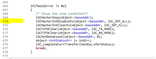
    In the issue scenario (Above scenario) , SOC sends stop. So, first we need to check why SOC sends a stop.

    You can put a breakpoint in the below function at lines 670 and 725.

    I2C_hwiFxnMaster

    And see why SOC is sending a STOP pulse to sensor .

    Regards,

    S.Anil.

  • Hello All,

    I have captured Today mail conversion in below.

    Hi Chuo,


    There are a couple of things around Interrupt priority that I wanted to check on.


    The debug steps below are inspired from AM64x TRM section named “R5FFSS Vectored Interrupt Manager”.

    I have gone through a couple of registers and I want you to do the same. Please follow along the steps:


    1. While the I2C Transaction is happening, please read the register “R5FFS_VIM_ACTIRQ”(Physical Address = “2FFF 0020h”). It would be nice of you to read the bits(9-0).
    2. The bits(9-0) will show the active interrupt number, which in your case should be 194.
    3. If the above observation is correct, then proceed to the next step.
    4. Read the register “R5FSS_VIM_PRI_INT_j”(Physical Address = “2FFF 130Ch”). This register will tell you about the priority number of I2C1_POINTRPEND_0(ID = 194). Read the bits(3-0).
    5. The bits(3-0) will tell you the priority number. [NOTE: Most probably the priority number would be from 0 to 15, with 0 being the highest priority and 15 being the lowest]
    6. Once you have the priority number, please convey the same information to us.


    In our first transaction, we are trying to send the following:


    wrData[0U] = 0x3EU;

    status = IO_I2C_writeRead(pDevice->device, wrData, 1U, rdData, 1U);


    Inside it will become:

    writeBuf: wrData (uint8_t array)

    writeCount: 1U

    readBuf: rdData (uint8_t array)

    readCount: 1U

    Device addr: 0x60

    Timeout: (TickType_t)1UL


    Thanks,

    Chuo

    -- 


    Hello Chuo,


    Thanks for sharing the details.

    We will suggest some proposals by EOD, and please perform the Testing and provide Test Results .

    Again, we will connect tomorrow.

    It would be good  if you could provide the following details.

    What are the writeLen, readLen, slave address, and timeout values you have configured in the below code?


    Regards,

    S.Anil.

    START + SA+W + ACK (Peripheral) + Register Address + ACK (Peripheral) + Repeated Start + SA + R + ACK + 1 Byte + ACK (Controller) + 2nd Byte + NACK (Controller) + STOP


    [Chuo] I believe this is what I2C_transfer() does.  Let me verify, and reply in the format you are looking for.


    Now, when you call this function in blocking mode, control is not coming out from  i2c_transfer , and Watchdog is doing the SOC Reset.


    In Callback mode control is coming but no watch dog Reset and data Read is not completed and Read buffer is empty.


    [Chuo] Yes that is inline with my observation.


    Thanks,

    Chuo


    Hello Chuo,


    In this function itself, you are sending commands and expecting to read data.


    START + SA+W + ACK (Peripheral) + Register Address + ACK (Peripheral) + Repeated Start + SA + R + ACK + 1 Byte + ACK (Controller) + 2nd Byte + NACK (Controller) + STOP


    I hope you are also following the same protocol. Please share the details of all writebuf, writebufcoun, and readcoun values.

    Please try to share details in the below form.


       I2C_Transaction_init(&i2cTransaction);


       i2cTransaction.writeBuf   = txBuffer;


      i2cTransaction.writeCount = 1;


    i2cTransaction.targetAddress = 0xC1;


    Now, when you call this function in blocking mode, control is not coming out from  i2c_transfer , and Watchdog is doing the SOC Reset.


    In Callback mode control is coming but no watch dog Reset and data Read is not completed and Read buffer is empty.


    Regards,

    S.Anil.

    Hi Anil,


    Here is the function we wrote to interact with your driver.  I2C_transfer() is the function within your driver.  All of the data communication goes through this function.


    Thanks,

    Chuo


    Hello Chuo,

    Please share the only I2C Application .c file to check  how you are reading data from the sensor.

    Regards,

    S.Anil.


  • We solved this on our end. We were trying to read/write I2C without the rtos running leading to data abort on semaphore operations.
    After resolving, the chip appears to be working without error codes from I2C.

  • Thanks Parth Patel .

    I am closing this thread and please open new thread if you have new quires .

    Regards,

    S.Anil.