This thread has been locked.

If you have a related question, please click the "Ask a related question" button in the top right corner. The newly created question will be automatically linked to this question.

AM6442: Compare router to trigger bcdma

Part Number: AM6442

Hello, 

I am using AM6442 board, on a no-RTOS, bare-metal system on Windows. 

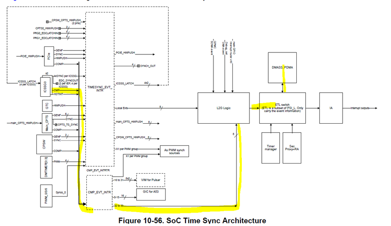
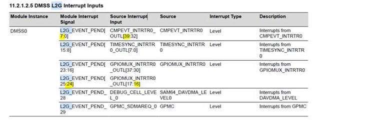
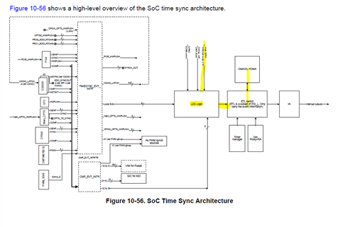
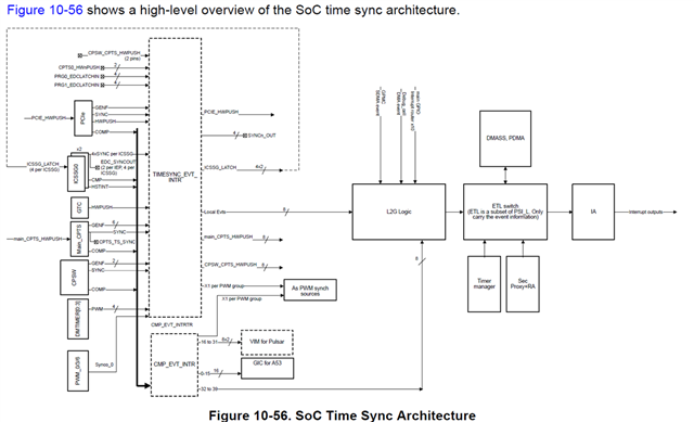
My final goal is to use GPMC to connect to an external FPGA and use the UDMA for transfers. So far I was able to read from GPMC with DMA while a software event triggers the start of transfer for BCDMA. Now I would like to define a timer to trigger the BCDMA transfer each 700us. I believe I should use the CMP_EVT_INT. But I don't know how should I do it. Can you give me a little detail about how I should do it? I would appreciate it if you could give me an example of how to use and define this CMP_EVT_INT and how to route it to trigger my BCDMA?

Thanks, 

Boshra

  • Hello Boshra,

    I have working code for your requirement and will share it by EOD since I am in training.

    Regards,

    S.Anil.

  • Hello Boshra,

    I have working code for your requirement.


    I am triggering DMA in the below sequence.

    IEP timer: > CMP_EVE_INTRR; > L2G; > DMASS0

    You have to follow the steps below.

    Step1 : 

    IEP timers are available in PRU cores, and you should enable PRU cores and IEP timers from the system configuration.

    You can look at an example system cfg for your reference.

    Step2: 

    Use any timer either IEP1 and IEP2 and select one CMP_EVENT among eight CMP_EVENTS .

    Step3: 

    Next, route CMP events to CMP_ENT_INTR; for that, we need to configure the SCI client since we can't write direct values into the INTR ROUTER Register.

    Please check out the example SCI client configuration function for your reference.

    Step4: 

    Converting local events to global event though there is L2G register and that we need to select local event no. and gloab event no.

    Please check out the L2G function for more details.

    To configure SCi client to route CMP EVENTS to CMP EVENT INTR Router, we need src index and dst index, and this information should be available in the link below.

    https://software-dl.ti.com/tisci/esd/latest/5_soc_doc/am64x/resasg_types.html

    And currently in the example, I am checking whether the timer is expired or not. If the timer is expired, I was assuming that UDMA data transfer completion was over and reading data from UDMA, but here, instead of checking the timer expiration status, you can use the status of the UDMA completion event.


    I have tried this example in the UDMA interrupt mode, but it is not working. So, I was checking the status of the timer before reading UDMA data.

    udma_memcpy_interrupt_am64x-evm_r5fss0-0_nortos_ti-arm-clang.zip

    Regards,

    S.Anil.

  • Thanks for your reply. 

    In step one by mentioning system configuration, do you mean this is kind of a board configuration and should be done in sciclient_ccs_init level before programming the application?

    Step1 : 

    IEP timers are available in PRU cores, and you should enable PRU cores and IEP timers from the system configuration.

    You can look at an example system cfg for your reference

  • In step one by mentioning system configuration, do you mean this is kind of a board configuration and should be done in sciclient_ccs_init level before programming the application?

    No, Boshra. You don't need to enable them in the board configuration.

    Just enable them in the system configuration file and generate code.

    Please check out the attached example.

    For your reference, I have attached the image below.

    Regards,

    S.Anil,

  • Hi, 

    Thanks for your reply. 

    I'm looking at the example you sent me. 

    I have a few questions. 

    So using these timers makes it necessary to use the PRU cores? There is no other outside the PRU that can trigger BCDMA? For example, GTC timers are not able to trigger BCDMA? 

    I believe BCDMA can also be triggered by GPIO from an external device. Do you have an example for that too? 

    Thanks, 

    Boshra

  • Boshara,

    So using these timers makes it necessary to use the PRU cores? There is no other outside the PRU that can trigger BCDMA? For example, GTC timers are not able to trigger BCDMA? 

    Yes, when you want the IEP timers, you should use the PRU cores.

    I have given an example based on the IEP timer and CMP_INTR router, which you can do for other timers with different interrupt routers.

    You can try with GTC Timer as well; there is a Hwpush event going to the Timer sync event interrupt router.

    I believe BCDMA can also be triggered by GPIO from an external device. Do you have an example for that too? 

    Yes, I have the example code ,

    You have to follow the steps below to work GPIO+UDMA example on EVM:

    1. Route GPIO interrupts to the MAIN GPIO interrupt router to trigger BCDMA/PDMA.

    2. Next, convert the local GPIO event into a global event.

    Software Changes : 

    1. Configure GPIO as an input based on your requirements.

    2. Enable GPIO Interrupt Routers 16 to 17 or 30 to 37. Since these routers only connected to L2G.

    Currently, in the software, these routers are not configured.

    So, I have manually updated only the GPIO-16 router in the sciclient_defaultBoardcfg_rm.c file.

    Folder Path: C:timcu_plus_sdk_am64x_08_05_00_24sourcedriverssciclientsciclient_default_boardcfgam64x_am243x

    3. Compile the sciclient_defaultBoardcfg_rm.c file.

    You have to give the below command to compile it.

    4. Compile SBL and Flash SBL with updated board config file 

    5. Run your Application from CCS .

    3056.empty_am64x-evm_r5fss0-0_nortos_ti-arm-clang (1) (1).zip

    BTW, I need to reproduce your GPMC issue on my HW and let you know.

    Regards,

    S.Anil.

  • And currently in the example, I am checking whether the timer is expired or not. If the timer is expired, I was assuming that UDMA data transfer completion was over and reading data from UDMA, but here, instead of checking the timer expiration status, you can use the status of the UDMA completion event

    Boshra, Please make sure that above point when you are integrating these examples in your Application.

    Regards,

    S.Anil.

  • Thank you so much for your explaination.

    You can try with GTC Timer as well; there is a Hwpush event going to the Timer sync event interrupt router.

    But does it still mean that I need to use the PRU cores? 

    3056.empty_am64x-evm_r5fss0-0_nortos_ti-arm-clang (1) (1).zip

    There is part of this code that is not clear to me. For tisci_msg_rm_irq_set_req, it has set the src_index to 92:

    #define TISCI_GPIO_BANK_INT_SRC_IDX_BASE_GPIO0      ( 90U )
    #define TISCI_GPIO_BANK_INT_SRC_IDX_BASE_GPIO1      ( 90U )
    #define TISCI_GPIO_BANK_INT_SRC_IDX_BASE_MCU_GPIO0  ( 30U )
    #define TISCI_GPIO1_BANK_INT_SRC_IDX(x)             ( TISCI_GPIO_BANK_INT_SRC_IDX_BASE_GPIO1 + x )

    However, when I check the TRM, I see that for GPIO1_GPIO43, the INTRR0_In is 133.

    where this 92 is coming from? 

    THanks, 

    Boshra

  • But does it still mean that I need to use the PRU cores? 

    No, it does not require a PRU core. It can be used as a 64-bit counter and is available on the Main Domain (A53 and R5F).

    But you need to stick time based on the PUSH event of the GTC timer, and that event should be configured from bit value 0 to 63.

    Other than GTC and IEP, we don't have any other timers to automatically trigger DMA.

    where this 92 is coming from? 

    In the above example, I was trying to enable the bank interrupt for the GPIO1_43 pin. If you see the below image in the TRM, GPIO1_43 comes under the Bank 2 interrupt number, and the router output would be 182. So, I need to send 182 values, but I was sending 92. Here is another 90 offset that will be taken care of by the sciclient irq set function.

    So, if you need the pin interrupt, just pass the pin number, and if you need the bank interrupt , it is 90 offset +  bank number and the final 90 offset value will be taken care of by the sciclient irq set function in both cases .

    the RM file of AM64X is divided GPIO pins into two groups

    1. GPIO 0 bank interrupts and pin interrupts

    2. GPIO1 bank interrupts and pin interrupts

    If you need more details, please go through this file so you can understand why an offset value is needed.

    File name : sciclient_irq_rm

    C:\ti\mcu_plus_sdk_am64x_09_00_00_31\source\drivers\sciclient\soc\am64x_am243x

    Regards,

    S.Anil.

  • Hi, 

    Thanks for your detailed explanation. It was very helpful. 

    I just have two more questions.

    Does it mean GPIO1_Pin43 Can generate interrupt both under pin interrupt (133), and also bank interrupt (182)?

    Also regarding the L2G, in this case you used L2G_EVENT[24] which corresponds to GPIOMUX_OUT_INTRTR0_OUTL[16]. and from the other hand in the sciclient set irq function we gave the L2G_EVENT[24] as well as the src interrupt which is GPIO1_BANK2_INT. So it means that instead of GPIO1_BANK2_INT we could give any other bank interrupt or pin interrupt that we wanted (that exist for main domain). Is that right?

    Thanks, 
    Boshra

  • Does it mean GPIO1_Pin43 Can generate interrupt both under pin interrupt (133), and also bank interrupt (182)?

    Boshra,

    Yes, your understanding is correct, but you can route either a pin interrupt or a bank interrupt to the GPIO MUX interrupt router output.

    So it means that instead of GPIO1_BANK2_INT we could give any other bank interrupt or pin interrupt that we wanted (that exist for main domain). Is that right?

    Yes, your understanding is correct. You can give any pin or bank interrupt; it should work. Make sure that GPIOMUX_OUT_INTRTR0_OUTL[16] output is properly configured in the rm_cfg.c file, as it is clearly stated in the above comments.

    Currently, in the software, these routers are not configured.

    So, I have manually updated only the GPIO-16 router in the sciclient_defaultBoardcfg_rm.c file.

    Folder Path: C:timcu_plus_sdk_am64x_08_05_00_24sourcedriverssciclientsciclient_default_boardcfgam64x_am243x

    3. Compile the sciclient_defaultBoardcfg_rm.c file.

    Regards,

    S.Anil.

  • Thanks

    It is clear now