This thread has been locked.

If you have a related question, please click the "Ask a related question" button in the top right corner. The newly created question will be automatically linked to this question.

TDA4AH-Q1: The GPIO interrupt is not responding

Part Number: TDA4AH-Q1
Other Parts Discussed in Thread: TDA4VH, TDA4VM

Hi Team,

When the consumer is debugging a peripheral, it does not respond after registering the interrupt. The peripheral hardware interrupt has been acknowledged to have a waveform that affects the level state of the interrupt line that can be read when set to input mode. 

DTS:

		gpio_irq = <&main_gpio0 24 GPIO_ACTIVE_HIGH>; /*gpio0_24 AE36*/

The location to call:

	client_data->gpio_pin = of_get_named_gpio_flags(
		client_data->dev->of_node,
		"gpio_irq", 0, NULL);
//	client_data->gpio_pin = 388;
	PINFO("%s gpio 2 number:%d\n", SENSOR_ACC_NAME, client_data->gpio_pin);
	if (client_data->gpio_pin < 0) {
		PINFO("%s return gpio number:%d\n", SENSOR_ACC_NAME, client_data->gpio_pin);
		err = client_data->gpio_pin;
		return err;
	}
	
#if 1
	err = gpio_request_one(client_data->gpio_pin,
				GPIOF_IN, "smi230_acc_interrupt");
	if (err < 0) {
		PDEBUG("gpio_request_one\n");
		return err;
	}
	err = gpio_direction_input(client_data->gpio_pin);
	if (err < 0) {
		PDEBUG("gpio_direction_input\n");
		return err;
	}
	
	printk("irq 2 %d\n",client_data->IRQ);
#endif	
	printk("irq 3 %d\n",client_data->IRQ);

	client_data->IRQ = gpio_to_irq(client_data->gpio_pin);
	printk("irq %d\n",client_data->IRQ);
	err = request_irq(client_data->IRQ, smi230_irq_handle,
			IRQF_TRIGGER_RISING,
			SENSOR_ACC_NAME, client_data);
	if (err < 0) {
		printk("request_irq %d\n",err);
		return err;
	}

The following interrupt counts are not incremented:

364:          0          0          0          0          0          0          0          0      GPIO  24 Edge    -davinci_gpio  SMI230ACC

WKUP_GPIO0_13 K38 is also used to test if interrupts are supported, but failed.

It's found that the corresponding interrupt is already set:
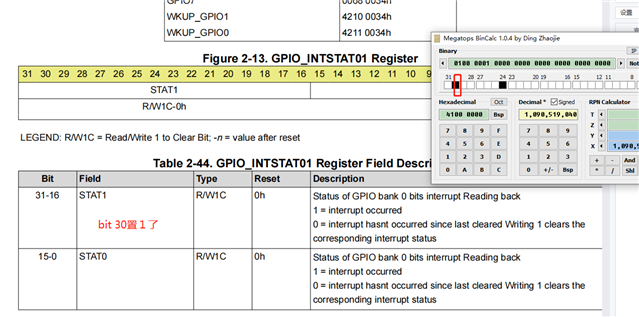
Clear and automatically set to 1:

Now the pin used is AE36, pinmux is set correctly: 

devmem2 0x0011C060
/dev/mem opened.
Memory mapped at address 0xffffaf991000.
Read at address  0x0011C060 (0xffffaf991060): 0x00050007

Could you please help check this case? Thanks.

Best Regards,

Cherry

  • Hi Cherry,

    To make sure GPIO is correctly pinmuxed on top of being defined for interrupt, and to check if the flow to enable interrupt is correct using Linux, could you follow this FAQ to see if you could replicate this on your system? https://e2e.ti.com/support/processors-group/processors/f/processors-forum/1058595/faq-tda4vm-how-to-test-gpio-interrupts

    Regards,

    Takuma

  • Hi Takuma,

    Thank you for the support.

    The customer tested with (AE36) GPIO0_24:

    diff --git a/board-support/linux-kernel/arch/arm64/boot/dts/ti/k3-j784s4-evm.dts b/board-support/linux-kernel/arch/arm64/boot/dts/ti/k3-j784s4-evm.dts
    index d7e846127..9c69bd834 100755
    --- a/board-support/linux-kernel/arch/arm64/boot/dts/ti/k3-j784s4-evm.dts
    +++ b/board-support/linux-kernel/arch/arm64/boot/dts/ti/k3-j784s4-evm.dts
    @@ -248,7 +248,11 @@ vdd_sd_dv: regulator-TLV71033 {
     		states = <1800000 0x0>,
     			 <3300000 0x1>;
     	};
    -
    +	gpio_test{
    +		compatible = "ti,gpio_test";
    +		interrupt-parent = <&main_gpio0>;
    +		interrupts = <24 IRQ_TYPE_EDGE_BOTH>;
    +	};
     	cpsw9g_virt_mac: main-r5fss-cpsw9g-virt-mac0 {
     		compatible = "ti,j721e-cpsw-virt-mac";
     		dma-coherent;
    @@ -747,6 +751,13 @@ mxt2113td: mxt2113td@4a {
     		status = "okay";
     	};
     };
     &mcu_i2c1 {
     	status = "okay";
     	pinctrl-names = "default";
    @@ -762,14 +773,14 @@ smi230gyro: smi230gyro@68 {
     	};
     	smi230acc: smi230acc@18 {
     		compatible = "SMI230ACC";
    -		pinctrl-names = "default";
    -		pinctrl-0 = <&imuacc_main_pins_default>;
    +		// pinctrl-names = "default";
    +		// pinctrl-0 = <&imuacc_main_pins_default>;
     		reg = <0x18>;
     		// pinctrl-0 = <&imuacc_pins_default>;
     
     		// gpio_irq = <&wkup_gpio0 13 IRQ_TYPE_EDGE_RISING>; /*gpio0_24 AE36*/
     		// gpio_irq = <&main_gpio0 24 0>; /*gpio0_24 AE36*/
    -		gpios = <&main_gpio0 24 0>;
    +		// gpios = <&main_gpio0 24 0>;
     		status = "okay";
     	};
     };
    @@ -930,7 +941,10 @@ &pcie1_ep {
     };
     
     &main_gpio0 {
    +	pinctrl-names = "default";
    +    pinctrl-0 = <&imuacc_main_pins_default>;
     	status = "okay";
    +
     };
     
     &main_gpio_intr {
    @@ -1364,6 +1378,8 @@ &dsi0 {
     };
     
     &wkup_gpio0 {
     	status = "okay";
     };
     
    diff --git a/board-support/linux-kernel/drivers/gpio/gpio-davinci.c b/board-support/linux-kernel/drivers/gpio/gpio-davinci.c
    index 0dca22c8d..6b5307360 100644
    --- a/board-support/linux-kernel/drivers/gpio/gpio-davinci.c
    +++ b/board-support/linux-kernel/drivers/gpio/gpio-davinci.c
    @@ -25,7 +25,11 @@
     #include <linux/pm_runtime.h>
     
     #include <asm-generic/gpio.h>
    +#include <linux/interrupt.h>
    +#include <linux/of_irq.h>
    +#include <linux/of_gpio.h>
     
    +int gpio_test_init(void);
     #define MAX_REGS_BANKS 5
     #define MAX_INT_PER_BANK 32
     
    @@ -189,7 +193,34 @@ davinci_gpio_get_pdata(struct platform_device *pdev)
     	dev_err(&pdev->dev, "Populating pdata from DT failed: err %d\n", ret);
     	return NULL;
     }
    +static irqreturn_t test_irq(int irq, void *data)
    +{
    +	printk("%s: irq %d, val=%d\n", __func__, irq,
    +		gpio_get_value(333));
    +	return IRQ_HANDLED;
    +}
    +
    +int gpio_test_init(void)
    +{
    +	struct device_node *np;
    +	int irq;
    +	int ret = 0;
    +
    +	np = of_find_node_by_name(NULL, "gpio_test");
    +
    +	if (np) {
    +		pr_info("Initializing gpio test\n");
    +		irq = irq_of_parse_and_map(np, 0);
    +		printk("irq number is %d\n", irq);
    +		ret = request_irq(irq, test_irq, //IRQF_TRIGGER_RISING,
    +				  IRQF_TRIGGER_FALLING | IRQF_TRIGGER_RISING,
    +				  "key-gpio", NULL);
    +		if (ret)
    +			pr_err("request_irq returns %d\n", ret);
    +	}
     
    +	return ret;
    +}
     static int davinci_gpio_probe(struct platform_device *pdev)
     {
     	int bank, i, ret = 0;
    @@ -197,7 +228,7 @@ static int davinci_gpio_probe(struct platform_device *pdev)
     	struct davinci_gpio_controller *chips;
     	struct davinci_gpio_platform_data *pdata;
     	struct device *dev = &pdev->dev;
    -
    +	printk("Name of gpio dev is %s\n", pdev->name);
     	pdata = davinci_gpio_get_pdata(pdev);
     	if (!pdata) {
     		dev_err(dev, "No platform data found\n");
    @@ -275,6 +306,9 @@ static int davinci_gpio_probe(struct platform_device *pdev)
     	ret = davinci_gpio_irq_setup(pdev);
     	if (ret)
     		return ret;
    +	if (!strcmp("600000.gpio", pdev->name)) {
    +		gpio_test_init();
    +	}
     
     	return 0;
     }

    devmem2 0x0011C060
    /dev/mem opened.
    Memory mapped at address 0xffff9563a000.
    Read at address 0x0011C060 (0xffff9563a060): 0x00050007

    It can be confirmed registration is successful.

    echo value

    The interrupt signals are as follows, but there is no interrupt response:

    There are no external interrupt sources and no interrupts are generated:

    Thanks and regards,

    Cherry

  • Hi Cherry,

    Looking through the patch file sent, I do not see pinmuxing. Can you also post the content of imuacc_main_pins_default node?

    Since it looks like main domain GPIO0_24 is being used, there should be something like "J784S4_IOPAD(0x060, PIN_INPUT, 7) /* (AE36) MCASP2_AXR1.GPIO0_24 */" under imuacc_main_pins_default. Please reference the FAQ in my previous post for an example of what the node should look like.

    Regards,

    Takuma

  • Hi Takuma,

    Can you also post the content of imuacc_main_pins_default node?

    	imuacc_main_pins_default: imuacc-main-pins-default {
    		pinctrl-single,pins = <
    			J784S4_IOPAD(0x060, PIN_INPUT, 7) /* (AE36) GPIO0_24 */
    		>;
    	};

    Please reference the FAQ in my previous post for an example of what the node should look like.

    According to the FAQ, the system does not respond to GPIO interrupts. The customer has ported the TP module to it (working in other sdk) and GPIO has not triggered an interrupt. System interrupts to GPIOs seems have no effect.

    Thanks and regards,

    Cherry 

  • Hi Cherry,

    Device tree looks to be defined correctly, so issue must be elsewhere.

    The customer has ported the TP module to it (working in other sdk)

    Could I get a reminder for which SDK version the customer is currently working on, and which SDK version the TP module was ported from? Also, apologies for my lack of knowledge, but could you clarify what "TP" stands for (ex. is it "Test Point")?

    Lastly, could you check one last common issue that customers face, which is that if GPIO is defined for RTOS usage, there would be a resource conflict and not allow Linux control of the GPIO? As an experiment, is the customer able to toggle the GPIO pin through software (assuming there is a test point designed in to verify the signal on this GPIO and this GPIO is fine to be configured as output)?

    Regards,

    Takuma

  • Hi Takuma,

    but could you clarify what "TP" stands for (ex. is it "Test Point")?

    It means "Touch".

    mxt2113td: mxt2113td@4a {
    compatible = "atmel,maxtouch";
    pinctrl-names = "default";
    // pinctrl-0 = <&ub941_initb_pins_default>;
    reg = <0x4a>;
    //gpios = <&porta 13 0>; /*gpio13 for touch irq*/
    gpios = <&main_gpio0 30 0>;/*AH37*/
    status = "okay";
    };

    Comment out the pimux associated with RTOS and it's verifyed that the pinmux is correct after powering on.

    AE36:

    As an experiment, is the customer able to toggle the GPIO pin through software (assuming there is a test point designed in to verify the signal on this GPIO and this GPIO is fine to be configured as output)?

    It can be verified that it dose soldered and the customer can read the GPIO value by setting pin AE36 to input (level triggered by external signal) 

    Thanks and regards,

    Cherry

  • Hi Cherry,

    The customer has ported the TP module to it (working in other sdk)

    Which SDK was the TP module working in, and which SDK is this ported over to? For example, is it ported over from TDA4VM PSDK Linux 8.5 version to TDA4VH PSDK RTOS 8.6 version? I would like to know whether this was working on a different device, OS, and/or version of the SDK, to see what differences could cause the device to work or not work.

    Comment out the pimux associated with RTOS

    Is the interrupt being handled in RTOS or Linux? If RTOS is handling the interrupt, Linux should not set up and hog the GPIO pin, and instead RTOS should be used to set up the pin.

    Regards,

    Takuma

  •  Hi Takuma,

    Which SDK was the TP module working in, and which SDK is this ported over to? For example, is it ported over from TDA4VM PSDK Linux 8.5 version to TDA4VH PSDK RTOS 8.6 version? I would like to know whether this was working on a different device, OS, and/or version of the SDK, to see what differences could cause the device to work or not work.

    "Touch" working sdk version is as follows:

    ti-processor-sdk-linux-j7-evm-07_03_00_05

    ti-processor-sdk-rtos-j7-evm-07_03_00_05

    Is the interrupt being handled in RTOS or Linux? If RTOS is handling the interrupt, Linux should not set up and hog the GPIO pin, and instead RTOS should be used to set up the pin.

    No GPIO interrupts are currently added to the corresponding SDK and the current SDK version for case issues is: 

    ti-processor-sdk-linux-j721s2-evm-08_06_00_10

    ti-processor-sdk-rtos-j721s2-evm-08_06_00_11

    Thanks and regards,

    Cherry

  • Hi Cherry,

    Understood, thanks for the clarification. It looks like there is a difference in SDK version as well as difference in device.

    As such, I think the first step is to isolate if the problem is due to differences in SDK version, or differences in device. Although I understand this is additional work for the customer, can they:

    1. Verify if they can move to 8.6 SDK on J721E, they can still use touch screen.
    2. After verifying step one, check to see if device differences are taken into account. For example, this FAQ summarizes differences in GPIO between J721E and J721S2: https://e2e.ti.com/f/791/t/1160537

    In the meantime, I will be doing some experiments on my end to also see if GPIO interrupt behaviors have changed between 7.3 and 8.6 SDK, and additionally check the differences in behavior between J721E and J721S2. This will most likely take me a couple of days, so please expect an update next week at the latest. However, in case the issue is not just GPIO interrupt related for enabling touch screen, I think the customer experiments with the touch screen on 8.6 SDK on J721E will be worthwhile.

    Regards,

    Takuma

  • Hi Takuma,

    For example, this FAQ summarizes differences in GPIO between J721E and J721S2: https://e2e.ti.com/f/791/t/1160537

    This is an internal FAQ, may I know if it's proper to disclose it with the customer?

    Thanks and regards,

    Cherry

  • Hi Cherry,

    Thanks for the notice. Yes, that is an internal FAQ which might not be appropriate in the public forum. However, the information in this FAQ can be used by the field team and for J721S2 there is no concern for disclosing the information about GPIO to customer.

    Regards,

    Takuma

  • Hi Cherry,

    I just noticed after reviewing our conversations, but is the customer using J721S2 (TDA4AL) or J784S4 (TDA4AH)? The thread was originally created for TDA4AH, but in our latest conversations it was mentioned J721S2 SDK is used.

    Can you confirm if the customer device is TDA4AH (for which the thread was originally created for), or TDA4AL (which is the device that the SDK being used is intended for)?

    Lastly, I did a quick experiment, in which I followed the interrupt FAQ (https://e2e.ti.com/support/processors-group/processors/f/processors-forum/1058595/faq-tda4vm-how-to-test-gpio-interrupts) for both 7.3 and 8.6 SDK. I found that behavior is the same on TDA4VM for both versions of SDK, so there seems to be not much change in terms of API when going from 7.3 to 8.6. Therefore, I think any issues customers are seeing is most likely due to the difference in SoC instead of difference in SDK.

    Regards,

    Takuma

  • Hi Takuma,

    I just noticed after reviewing our conversations, but is the customer using J721S2 (TDA4AL) or J784S4 (TDA4AH)? The thread was originally created for TDA4AH, but in our latest conversations it was mentioned J721S2 SDK is used.

    Can you confirm if the customer device is TDA4AH (for which the thread was originally created for), or TDA4AL (which is the device that the SDK being used is intended for)?

    Thank you for the confirmation and I've checked with the customer actually the debug hardware corresponds to tda4vh, SDK ti-processor-SDK-Linux-j784s4-EVM-08_06_00_12, sorry for the typo in the above responses.

    Therefore, I think any issues customers are seeing is most likely due to the difference in SoC instead of difference in SDK.

    So would it be an issue with SDK compatibility with different SoC for interrupt subsystem? 

    Thanks and regards,

    Cherry

  • Hi Cherry,

    So would it be an issue with SDK compatibility with different SoC for interrupt subsystem? 

    Possibly. However, it could also still be that the GPIO pin that we are trying to configure is used by another process on the J784S4, and in customer application these board/device related changes are not taken into consideration.

    For example, if I try to run the FAQ example using the same pin that is used in the FAQ on J784S4, I get the following logs:

    root@j784s4-evm:~# dmesg | grep gpio
    [ 1.010580] Name of gpio dev is 42110000.gpio
    [ 1.015349] Name of gpio dev is 600000.gpio
    [ 2.776707] Name of gpio dev is 42110000.gpio
    [ 2.782621] Initializing gpio test
    [ 2.791174] Name of gpio dev is 600000.gpio
    [ 4.719752] pinctrl-single 4301c000.pinctrl: pin PIN36 already requested by 42110000.gpio; cannot claim for 46000000.ethernet
    root@j784s4-evm:~#

    However, since I am also having other troubles porting over the FAQ example to J784S4, it could be that there is a change in API or the driver. I am still in the process of figuring out what the difference is, but please let me know what experiments the customer is trying out as well.

    Regards,

    Takuma

  • Hi Cherry,

    The interrupt router configuration is wrong in 8.6 SDK. This is fixed in 9.0 SDK.

    Here are the 2 patches:

    commit 68ec7433794c13da14e803b477ac6eefd330f243
    Author: Dasnavis Sabiya <sabiya.d@ti.com>
    Date:   Tue Jun 27 16:21:51 2023 +0530
    
        arm64: dts: ti: k3-j784s4: Fix the interrupt ranges property for main gpio intr
        
        The parent's input irq number is incorrect for the main_gpio_intr.
        Update the irq number as per the exact numbers in:
        https://software-dl.ti.com/tisci/esd/latest/5_soc_doc/j784s4/interrupt_cfg.html
        
        Fixes: bebe2e3c9a30i ("arm64: dts: ti: Add initial support for J784S4 SoC")
        
        Signed-off-by: Dasnavis Sabiya <sabiya.d@ti.com>
        Reviewed-by: Apurva Nandan <a-nandan@ti.com>
    
    diff --git a/arch/arm64/boot/dts/ti/k3-j784s4-main.dtsi b/arch/arm64/boot/dts/ti/k3-j784s4-main.dtsi
    index 2baac35dca2d..b6f40e7f7e13 100644
    --- a/arch/arm64/boot/dts/ti/k3-j784s4-main.dtsi
    +++ b/arch/arm64/boot/dts/ti/k3-j784s4-main.dtsi
    @@ -112,7 +112,7 @@
                    #interrupt-cells = <1>;
                    ti,sci = <&sms>;
                    ti,sci-dev-id = <10>;
    -               ti,interrupt-ranges = <8 360 56>;
    +               ti,interrupt-ranges = <8 392 56>;
            };


    The above is for main domain GPIO interrupts.

    commit f1ae38221253b800032585deff26e017615e5e5e
    Author: Apelete Seketeli <aseketeli@baylibre.com>
    Date:   Tue Apr 18 10:58:36 2023 +0200
    
        arm64: dts: ti: k3-j784s4-evm: Fix wakeup gpio pinmux interrupt range
        
        This patch fixes the interrupt range of wakeup gpio used by TPS6594 PMIC.
        
        Signed-off-by: Apelete Seketeli <aseketeli@baylibre.com>
        Signed-off-by: Esteban Blanc <eblanc@baylibre.com>
        Signed-off-by: Vignesh Raghavendra <vigneshr@ti.com>
    
    diff --git a/arch/arm64/boot/dts/ti/k3-j784s4-mcu-wakeup.dtsi b/arch/arm64/boot/dts/ti/k3-j784s4-mcu-wakeup.dtsi
    index f04fcb614cbe..ec4330f5dbb8 100644
    --- a/arch/arm64/boot/dts/ti/k3-j784s4-mcu-wakeup.dtsi
    +++ b/arch/arm64/boot/dts/ti/k3-j784s4-mcu-wakeup.dtsi
    @@ -65,7 +65,7 @@
                    #interrupt-cells = <1>;
                    ti,sci = <&sms>;
                    ti,sci-dev-id = <177>;
    -               ti,interrupt-ranges = <16 928 16>;
    +               ti,interrupt-ranges = <16 960 16>;
            };
     
            mcu_conf: syscon@40f00000 {

    The above is for wake up domain.

    Best Regards,
    Keerthy

  • Hi Keerthy,

    Thank you for the help!

    These interrupt ranges are not found in the TRM. The customer would like to know where can they find these information. 

    Thanks and Regards,

    Cherry

  • Hi Cherry,

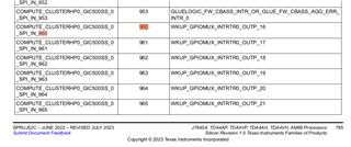
    This was a mistake in our SDK, so customers should not have had to go through the TRM for this. However, if they are interested in learning how to correlate the DTS file changes with the information in the TRM, I would recommend re-reading section 9.3 Interrupt Router in the TRM. For example, interrupt ID 960 is the start of the interrupts with 16th WKUP_GPIOMUX as the source interrupt:

    Likewise, interrupt ID 392 is the start of the interrupts with 8th GPIOMUX as the source interrupt:

    Regards,

    Takuma