This thread has been locked.

If you have a related question, please click the "Ask a related question" button in the top right corner. The newly created question will be automatically linked to this question.

SK-AM62: No SPI signals on expansion headers

Part Number: SK-AM62

Hello!

I made the following changes to enable SPI0 pins on the expansion header:

diff --git a/arch/arm64/boot/dts/ti/k3-am62x-sk-common.dtsi b/arch/arm64/boot/dts/ti/k3-am62x-sk-common.dtsi
index 7d0265531920b..760aaf70a5d53 100644
--- a/arch/arm64/boot/dts/ti/k3-am62x-sk-common.dtsi
+++ b/arch/arm64/boot/dts/ti/k3-am62x-sk-common.dtsi
@@ -16,6 +16,7 @@ aliases {
                serial2 = &main_uart0;
                 serial3 = &mcu_uart0;
                 serial5 = &main_uart5;
+                main_spi0 = &main_spi0;
                mmc0 = &sdhci0;
                mmc1 = &sdhci1;
                mmc2 = &sdhci2;
@@ -204,6 +205,14 @@ AM62X_IOPAD(0x1dc, PIN_OUTPUT, 1) /* uart5 txd */
                >;
        };
 
+        main_spi0_pins_default: main-spi0-pins-default {
+               pinctrl-single,pins = <
+                       AM62X_IOPAD(0x01bc, PIN_OUTPUT, 0) /* (A14) SPI0_CLK */
+                       AM62X_IOPAD(0x01c0, PIN_OUTPUT, 0) /* (B13) SPI0_D0 */
+                       AM62X_IOPAD(0x01c4, PIN_INPUT, 0) /* (B14) SPI0_D1 */
+                       AM62X_IOPAD(0x01b4, PIN_OUTPUT, 0) /* (A13) SPI0_CS0 */
+               >;
+       };
 
        main_i2c0_pins_default: main-i2c0-pins-default {
                pinctrl-single,pins = <
@@ -383,6 +392,17 @@ &main_uart5 {
        pinctrl-0 = <&main_uart5_pins_default>;
 };
 
+&main_spi0 {
+        status = "okay";
+        pinctrl-names = "default";
+        pinctrl-0 = <&main_spi0_pins_default>;
+        spidev@0 {
+                spi-max-frequency = <10000000>;
+                reg = <0>;
+                compatible = "rohm,dh2228fv";
+        };
+};
+

I then cross compiled the tools/spi/spidev_test application from the kernel tree and am running it this way:

.root@am62xx:~# ./spidev_test  -D /dev/spidev1.0 -s 100000 -p aa55aa55
spi mode: 0x0
bits per word: 8
max speed: 100000 Hz (100 kHz)

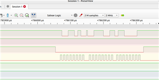
However, when I probe the clock pin (pin 23 on expansion slot) or the D0 pin (pin 19), I don't see any signals. Is there any other settings that I missed on the above device tree definitions?

Thanks

Ram

  • Hi Ram,

    you seem to be doing all the right things from a pinmux / pin-access and spidev_test usage POV, but without trying it myself it's hard to say if there isn't still some small detail missing.

    Some ideas for you to experiment with and report back:

    • There's actually a SPI device DTS example that exposes SPI0 through the user expansion header on the SK-AM62 board and the same pins you have part of the SDK v9.x Kernel tree, please see here https://git.ti.com/cgit/ti-linux-kernel/ti-linux-kernel/tree/arch/arm64/boot/dts/ti/k3-am625-sk-mcspi-loopback.dtso?h=ti-linux-6.1.y
      • Try using this as-is, to see if that helps
      • One thing I see that's different this DTS fragment explicitly declares #address-cells = <1>; and #size-cells = <0>;
      • The DTS fragment also turns on 3.3V power on the header, but this should not matter for what you are doing
    • Please double check you are probing the header pins, and your measurement equipment/logic analyzer is setup correctly and in good working condition
    • Try reducing the frequency setting to like 1MHz via spi-max-frequency

    If you still can't get that to work please post your kernel boot log.

    Regards, Andreas

  • Thanks Andreas. On some other forum post, I saw that the SPI0_CLK pin is configured as input. I tried that as well. I was expecting an SPI master to drive the clock to the slaves. So, I am not sure if that is also worth trying..

    I see some signals on the D0 when I probe the pins. But I do not see anything on the clock signal.

    May be I will also try (in addition to the steps you mentioned above), the spidev_test's -loop option and connect D0 to D1 via a jumper wire?

    Thanks again.

    Ram

  • Thanks Andreas. On some other forum post, I saw that the SPI0_CLK pin is configured as input. I tried that as well

    Actually that is a good point. Yes the SPI0_CLK module signal needs to be configured as "input" as this will turn on the associated RXACTIVE bit of the pad control register, see this note here in the TRM:

    It is also configured like this in the DTS example I liked to earlier at git.ti.com/.../k3-am625-sk-mcspi-loopback.dtso

    But I do not see anything on the clock signal.

    Try reducing the clock speed, perhaps the clock is too fast for whatever DSO you connect or the way it's configured. Then double check you have the right pin.

    May be I will also try (in addition to the steps you mentioned above), the spidev_test's -loop option and connect D0 to D1 via a jumper wire?

    Yes please try this as well.

    Regards, Andreas

  • Thanks Andreas. I got it to work after tinkering with the dtsi a bit. Here is the diff for anyone else who is trying it.

    diff --git a/arch/arm64/boot/dts/ti/k3-am62x-sk-common.dtsi b/arch/arm64/boot/dts/ti/k3-am62x-sk-common.dtsi
    index 7d0265531920b..feaf27c71f1ab 100644
    --- a/arch/arm64/boot/dts/ti/k3-am62x-sk-common.dtsi
    +++ b/arch/arm64/boot/dts/ti/k3-am62x-sk-common.dtsi
    @@ -16,6 +16,7 @@ aliases {
                    serial2 = &main_uart0;
                     serial3 = &mcu_uart0;
                     serial5 = &main_uart5;
    +                main_spi0 = &main_spi0;
                    mmc0 = &sdhci0;
                    mmc1 = &sdhci1;
                    mmc2 = &sdhci2;
    @@ -204,6 +205,14 @@ AM62X_IOPAD(0x1dc, PIN_OUTPUT, 1) /* uart5 txd */
                    >;
            };
     
    +        main_spi0_pins_default: main-spi0-pins-default {
    +               pinctrl-single,pins = <
    +                       AM62X_IOPAD(0x01bc, PIN_OUTPUT, 0) /* (A14) SPI0_CLK */
    +                       AM62X_IOPAD(0x01c0, PIN_OUTPUT, 0) /* (B13) SPI0_D0 */
    +                       AM62X_IOPAD(0x01c4, PIN_INPUT, 0) /* (B14) SPI0_D1 */
    +                       AM62X_IOPAD(0x01b4, PIN_OUTPUT, 0) /* (A13) SPI0_CS0 */
    +               >;
    +       };
     
            main_i2c0_pins_default: main-i2c0-pins-default {
                    pinctrl-single,pins = <
    @@ -383,6 +392,20 @@ &main_uart5 {
            pinctrl-0 = <&main_uart5_pins_default>;
     };
     
    +&main_spi0 {
    +        status = "okay";
    +       #address-cells = <1>;
    +       #size-cells = <0>;
    +        pinctrl-names = "default";
    +        pinctrl-0 = <&main_spi0_pins_default>;
    +        ti,pindir-d0-out-d1-in=<0>;
    +        spidev@0 {
    +                spi-max-frequency = <1000000>; /* 1 MHz */
    +                reg = <0>;
    +                compatible = "rohm,dh2228fv";
    +        };
    +};
    +
     &main_i2c0 {

            status = "okay";
            pinctrl-names = "default";

    Attaching the logic analyzer signals..

    spi signals

    Thanks once again for the guidance and help.

    Ram

  • Hi Ram,

    thanks for closing the loop, I do appreciate it. Good to see that it works, but for the record SPI0_CLK  should be set to PIN_INPUT, to enable that pad's RXACTIVE bit, as per TRM guidance (even "input" may seem counter-intuitive).

    I guess looking what you have now "working" vs, previously the only thing that spikes out are the additions of the #address-cells = <1>; and #size-cells = <0>; properties.

    Furthermore please note that ti,pindir-d0-out-d1-in is a boolean property. So don't assign anything to that, because the value will get ignored. See how it's used in other DTS files.

    Regards, Andreas

  • Thanks Andreas. I made those changes (clk as input and the d0-out, d1-in property) and it works fine. Thanks so much once again.