This thread has been locked.

If you have a related question, please click the "Ask a related question" button in the top right corner. The newly created question will be automatically linked to this question.

TDA4VH-Q1: TDA4VH cascaded camera problem

Part Number: TDA4VH-Q1

Hi,

TI experts,

We are debugging two TDA4 cascaded drivers.

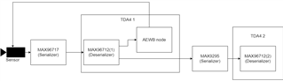
We want to use the link shown in the figure below to let the camera output images on the second TDA4, but there are some problems. 

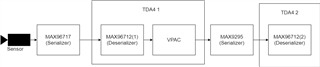
On TDA4 1, we use the deserializer MAX96712(1) to receive the data from the camera module (Sensor and serializer MAX96717), and then copy the data output by the deserializer into two channels (MAX96712 has a data copy function and can output two identical channels. data).

We output the first channel to TDA4 1 and use VPAC to adjust the AEWB, output the second channel to the serializer MA9295, and then output it to the MAX96712(2)  on TDA4 2.

We use TDA4 2 to configure the registers of the serializer MAX9295 and the deserializer MAX96712(2), and regard the data input in the previous section as a camera with its own ISP.

But when we try to use the single cam demo app to output images on the TDA4 2, no data is received, and there is no obvious error in the logs printed by the app and RTOS.

We use an oscilloscope to measure the MIPI signal output by MAX96712(2), which is a normal 30Hz signal. And we can confirm that the two channels of data output by the deserializer on TDA4 1 are normal, and the saved pictures are also normal. 

In addition, we have used the same serializer and deserializer configuration to successfully output the image on the Rolongo, but now we cannot receive any data on the TDA4 2.

Does a link like this TDA4 receive data correctly? Do any modifications need to be made to the driver and app? How do we debug?

Thanks.

  • Hi,

    A few followup questions to understand the issue better.

    We output the first channel to TDA4 1 and use VPAC to adjust the AEWB, output the second channel to the serializer MA9295, and then output it to the MAX96712(2)  on TDA4 2

    In the diagram, it is seen that the output of VPAC is going to the serializer MAX9295, whereas in the above description, you have mentioned that there are 2 channels from MAX96712 (1), one to VPAC and other to MAX9295.

    Could you please clarify the above? The diagram does not show this 2 channel output.

    But when we try to use the single cam demo app to output images on the TDA4 2, no data is received, and there is no obvious error in the logs printed by the app and RTOS

    May I know what is the input format received at TDA4 2?

    Do you see any errors in the csirx stats? (Such as overflow / underflow etc.. )

    Are you using single cam demo as it is? or have you integrated it with another application that would take in the input for TDA4 (1) ?

    Regards,

    Nikhil

  • Hi, Nikhil, 

    Could you please clarify the above? The diagram does not show this 2 channel output.

    I''m sorry, my understanding is wrong here. I reconfirmed and the correct picture should be as shown below:

    Channel 1 of MAX96712(1) is output to TDA4 1, and the exposure and white balance are adjusted through the AEWB node (here, the register value of the sensor is directly modified). The channel 2 output is directly input to MAX9195 without passing through VPAC. 

    May I know what is the input format received at TDA4 2?

    The input format reveived at TDA4 2 should be RAW12. 

    Do you see any errors in the csirx stats? (Such as overflow / underflow etc.. )

    When I press "x" to exit the single cam demo, it gets stuck, I can't see the last stats, but I find this warning: 

    VX_ZONE_WARNING:[tivxCaptureSetTimeout:796]  CAPTURE: WARNING: Error frame not provided using tivxCaptureRegisterErrorFrame, defaulting to waiting forever !!!

    Are you using single cam demo as it is? or have you integrated it with another application that would take in the input for TDA4 (1) ?

    Both TDA4 1 and TDA4 2 use single cam demo. 

  • Hi,

    We use an oscilloscope to measure the MIPI signal output by MAX96712(2), which is a normal 30Hz signal

    Are you getting the MIPI data at the output of this deserializer?

    Could you please also confirm if the MAX9295 serializer has been configured correctly?

    Based on your inputs, the data coming to the second TDA4 should be same as that is coming directly from the sensor, right?

    Regards,

    Nikhil