

Hi,
I would like to ask a question on DM6437’s PSC configuration.
|
psc_change_state( int id, int state ) { #define PSC_PTCMD *( unsigned int* )( 0x01c41120 ) #define PSC_PTSTAT *( unsigned int* )( 0x01c41128 ) unsigned int* mdstat = ( unsigned int* )( 0x01c41800 + ( 4 * id ) ); unsigned int* mdctl = ( unsigned int* )( 0x01c41a00 + ( 4 * id ) );
/* * Step 0 - Ignore request if the state is already set as is */ if ( ( *mdstat & 0x1f ) == state ) // 0x1f = 00000000 00000000 00000000 00011111 b return;
/* * Step 1 - Wait for PTSTAT.GOSTAT to clear */ while( PSC_PTSTAT & 1 );
/* * Step 2 - Set MDCTLx.NEXT to new state */ *mdctl &= ~0x1f; // ~0x1f = 11111111 11111111 11111111 11100000 b *mdctl |= state;
/* * Step 3 - Start power transition ( set PTCMD.GO to 1 ) */ PSC_PTCMD = 1;
/* * Step 4 - Wait for PTSTAT.GOSTAT to clear */ while( PSC_PTSTAT & 1 );
/* * Step 5 - Verify state changed */ while( ( *mdstat & 0x1f ) != state ); } |
Above is the code for PSC state change from SEED, which is in turn based on Spectrum’s code. The questions are with bit operations. Information for these registers, particular mdstat and mdctl, can be found on sec.6.7 of SPRU978E, TMS320DM643x DMP DSP Subsystem Reference Guide (Rev. E).
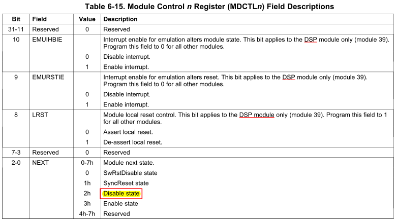
mdctl
Why the last five bits are cleared rather than two? According to Table 6-15, bits[7:3] are reserved, so bits[4:3] are also reserved. Why the code above still bothers to set them to zero first before setting the NEXT state in the next line?
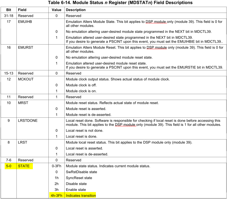
mdstat
According to Table 6-14, state bits are bits[5:0], which in all 6 bits up to limit 0x3f = 11 1111b. Also according to the table, bits[5:2] are useful bits rather than undefined bits because 4h~3Fh indicate transitions, so I don’t think any of bits [5:2] should be omitted from the module power status check. Therefore, the more reasonable way seems should be checking the LSB 6 bits [5:0], rather than only checking bits [4:0] here in the code. Is it correct?
A further question is that since according to Table 6-14 4h~3Fh of bits[5-0] indicate transitions, what does each of the values in the range indicate, and how should I check that?
Thanks,
Zheng