Hi, TI expert!
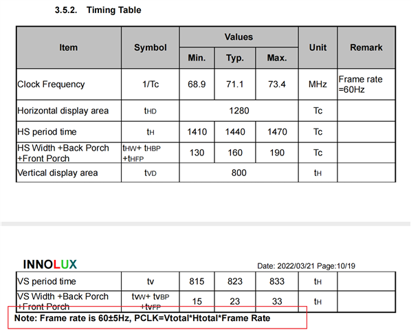
I have an LVDS screen, and the parameters of the screen are shown in the figure below:
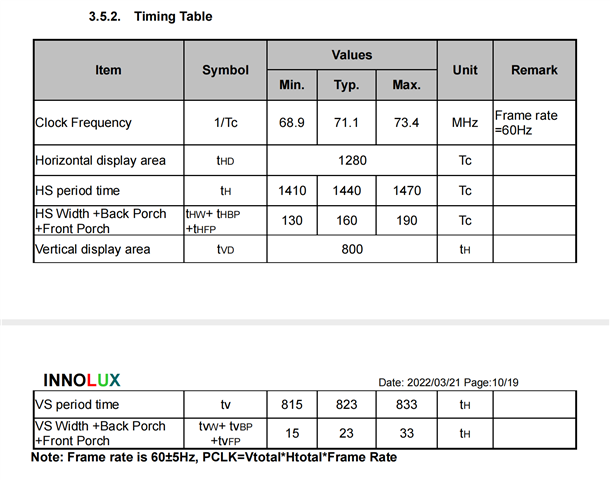

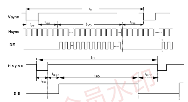
The corresponding DTS configuration is as follows:
// SPDX-License-Identifier: GPL-2.0
/**
 * DT overlay for OLDI in main domain on AM62x SK
 *
 * Copyright (C) 2022 Texas Instruments Incorporated - https://www.ti.com/
 */

#include <dt-bindings/pinctrl/k3.h>

&{/} {
	lvds_bl: backlight {
		compatible = "pwm-backlight";
		status = "okay";

		brightness-levels = <
			  0  20  20  21  21  22  22  23
			 23  24  24  25  25  26  26  27
			 27  28  28  29  29  30  30  31
			 31  32  32  33  33  34  34  35
			 35  36  36  37  37  38  38  39
			 40  41  42  43  44  45  46  47
			 48  49  50  51  52  53  54  55
			 56  57  58  59  60  61  62  63
			 64  65  66  67  68  69  70  71
			 72  73  74  75  76  77  78  79
			 80  81  82  83  84  85  86  87
			 88  89  90  91  92  93  94  95
			 96  97  98  99 100 101 102 103
			104 105 106 107 108 109 110 111
			112 113 114 115 116 117 118 119
			120 121 122 123 124 125 126 127
			128 129 130 131 132 133 134 135
			136 137 138 139 140 141 142 143
			144 145 146 147 148 149 150 151
			152 153 154 155 156 157 158 159
			160 161 162 163 164 165 166 167
			168 169 170 171 172 173 174 175
			176 177 178 179 180 181 182 183
			184 185 186 187 188 189 190 191
			192 193 194 195 196 197 198 199
			200 201 202 203 204 205 206 207
			208 209 210 211 212 213 214 215
			216 217 218 219 220 221 222 223
			224 225 226 227 228 229 230 231
			232 233 234 235 236 237 238 239
			240 241 242 243 244 245 246 247
			248 249 250 251 252 253 254 255
		>;

		default-brightness-level = <200>;
	};

	display {
		compatible = "panel-lvds";
		backlight = <&lvds_bl>;

		width-mm = <217>;
		height-mm = <136>;

		data-mapping = "vesa-24";

		panel-timing {
			clock-frequency = <72000000>;
			hactive = <1280>;
			vactive = <800>;

			hfront-porch = <80>;
			hsync-len = <20>;
			hback-porch = <60>;

			vfront-porch = <12>;
			vsync-len = <4>;
			vback-porch = <6>;

			hsync-active = <0>;
			vsync-active = <0>;
			de-active = <1>;
			pixelclk-active = <1>;
		};

		port@0 {
			lcd_in0: endpoint {
				remote-endpoint = <&oldi_out0>;
			};
		};

		port@1 {
			lcd_in1: endpoint {
				remote-endpoint = <&oldi_out1>;
			};
		};
	};
};

&main_pmx0 {
	main_oldi0_pins_default: main-oldi0-pins-default {
		pinctrl-single,pins = <
			AM62X_IOPAD(0x0260, PIN_OUTPUT, 0) /* (AA5) OLDI0_A0N */
			AM62X_IOPAD(0x025c, PIN_OUTPUT, 0) /* (Y6) OLDI0_A0P */
			AM62X_IOPAD(0x0268, PIN_OUTPUT, 0) /* (AD3) OLDI0_A1N */
			AM62X_IOPAD(0x0264, PIN_OUTPUT, 0) /* (AB4) OLDI0_A1P */
			AM62X_IOPAD(0x0270, PIN_OUTPUT, 0) /* (Y8) OLDI0_A2N */
			AM62X_IOPAD(0x026c, PIN_OUTPUT, 0) /* (AA8) OLDI0_A2P */
			AM62X_IOPAD(0x0278, PIN_OUTPUT, 0) /* (AB6) OLDI0_A3N */
			AM62X_IOPAD(0x0274, PIN_OUTPUT, 0) /* (AA7) OLDI0_A3P */
			AM62X_IOPAD(0x0280, PIN_OUTPUT, 0) /* (AC6) OLDI0_A4N */
			AM62X_IOPAD(0x027c, PIN_OUTPUT, 0) /* (AC5) OLDI0_A4P */
			AM62X_IOPAD(0x0288, PIN_OUTPUT, 0) /* (AE5) OLDI0_A5N */
			AM62X_IOPAD(0x0284, PIN_OUTPUT, 0) /* (AD6) OLDI0_A5P */
			AM62X_IOPAD(0x0290, PIN_OUTPUT, 0) /* (AE6) OLDI0_A6N */
			AM62X_IOPAD(0x028c, PIN_OUTPUT, 0) /* (AD7) OLDI0_A6P */
			AM62X_IOPAD(0x0298, PIN_OUTPUT, 0) /* (AD8) OLDI0_A7N */
			AM62X_IOPAD(0x0294, PIN_OUTPUT, 0) /* (AE7) OLDI0_A7P */
			AM62X_IOPAD(0x02a0, PIN_OUTPUT, 0) /* (AD4) OLDI0_CLK0N */
			AM62X_IOPAD(0x029c, PIN_OUTPUT, 0) /* (AE3) OLDI0_CLK0P */
			AM62X_IOPAD(0x02a8, PIN_OUTPUT, 0) /* (AE4) OLDI0_CLK1N */
			AM62X_IOPAD(0x02a4, PIN_OUTPUT, 0) /* (AD5) OLDI0_CLK1P */
		>;
	};

	lvds0_rst_pins_default: lvds0-rst-pins-default {
		pinctrl-single,pins = <
			AM62X_IOPAD(0x0094, PIN_OUTPUT, 7) /* (N20) GPMC0_BE1n.GPIO0_36 */
		>;
	};

	lvds1_rst_pins_default: lvds1-rst-pins-default {
		pinctrl-single,pins = <
			AM62X_IOPAD(0x0098, PIN_OUTPUT, 7) /* (U23) GPMC0_WAIT0.GPIO0_37 */
		>;
	};

	lvds1_bl_en_pins_default: lvds1-bl-en-pins-default {
		pinctrl-single,pins = <
			AM62X_IOPAD(0x00f0, PIN_OUTPUT, 7) /* (Y22) VOUT0_DATA14.GPIO0_59 */
		>;
	};

	lvds_bl_pwm_pins_default: lvds-bl-pwm-pins-default {
		pinctrl-single,pins = <
			AM62X_IOPAD(0x01a0, PIN_OUTPUT, 6) /* (E18) MCASP0_AXR0.EHRPWM1_B */
		>;
	};

	lvds0_touch_int_pin_default: lvds0-touch-int-pin-default {
		pinctrl-single,pins = <
			AM62X_IOPAD(0x0088, PIN_INPUT, 7) /* (L24) GPMC0_OEn_REn.GPIO0_33 */ /* CAP0_INT */
		>;
	};

	lvds1_touch_rst_pin_default: lvds1-touch-rst-pin-default {
		pinctrl-single,pins = <
			AM62X_IOPAD(0x00f8, PIN_OUTPUT, 7) /* (AB24) VOUT0_HSYNC.GPIO0_61 */ /* CAP1_RST */
		>;
	};

	lvds1_touch_int_pin_default: lvds1-touch-int-pin-default {
		pinctrl-single,pins = <
			AM62X_IOPAD(0x00f4, PIN_INPUT, 7) /* (AA21) VOUT0_DATA15.GPIO0_60 */ /* CAP1_INT */
		>;
	};
};

&mcu_pmx0 {
	lvds0_touch_rst_pin_default: lvds0-touch-rst-pin-default {
		pinctrl-single,pins = <
			AM62X_MCU_IOPAD(0x0030, PIN_OUTPUT, 7) /* (A4) WKUP_UART0_RTSn.MCU_GPIO0_12 */ /* CAP0_RST */
		>;
	};
};

&epwm1 {
	status = "okay";
};

&lvds_bl {
	pinctrl-names = "default";
	pinctrl-0 = <&lvds1_bl_en_pins_default &lvds_bl_pwm_pins_default>;

	pwms = <&epwm1 1 25000 0>;
	pwm-names = "backlight";

	enable-gpios = <&main_gpio0 59 GPIO_ACTIVE_HIGH>; //lvds1
};


&dss {
	pinctrl-names = "default";
	pinctrl-0 = <&lvds0_rst_pins_default &lvds1_rst_pins_default &main_oldi0_pins_default>;
};

&dss_ports {
	#address-cells = <1>;
	#size-cells = <0>;

	/* VP0: LVDS Output (OLDI TX 0) */
	port@0 {
		reg = <0>;
		oldi_out0: endpoint {
			remote-endpoint = <&lcd_in0>;
		};
	};

	/* VP1: LVDS Output (OLDI TX 1) */
	port@2 {
		reg = <2>;
		oldi_out1: endpoint {
			remote-endpoint = <&lcd_in1>;
		};
	};
};

&main_i2c1 {
	touchscreen@14 {
		compatible = "goodix,gt9xx";
		reg = <0x14>;
		status = "okay";

		pinctrl-names = "default";
		pinctrl-0 = <&lvds0_touch_rst_pin_default &lvds0_touch_int_pin_default>;

		interrupt-parent = <&main_gpio0>;
		interrupts = <33 IRQ_TYPE_EDGE_FALLING>;

		goodix,irq-gpio = <&main_gpio0 33 GPIO_ACTIVE_HIGH>;
		goodix,rst-gpio = <&mcu_gpio0 12 GPIO_ACTIVE_HIGH>;

		goodix,cfg-group0 = [
			5F 00 05 20 03 05 0F 00 01 0F 28
			0F 50 32 03 05 00 00 00 00 00 00
			00 00 00 00 00 8C 2E 0E 53 55 0C
			08 00 00 00 03 02 1D 00 01 00 00
			00 03 64 32 00 00 00 0F 78 94 C5
			02 07 00 00 04 A0 12 00 6A 1C 00
			47 2B 00 30 41 00 22 63 00 22 00
			00 00 00 00 00 00 00 00 00 00 00
			00 00 00 00 00 00 00 00 00 00 00
			00 00 00 00 00 00 00 00 00 00 00
			00 00 02 04 06 08 0A 0C 0E 10 12
			14 16 18 1A 1C 00 00 00 00 00 00
			00 00 00 00 00 00 00 00 00 00 00
			02 04 06 08 0A 0C 0F 10 12 13 14
			16 18 1C 1D 1E 1F 20 21 22 24 26
			28 29 2A 00 00 00 00 00 00 00 00
			00 00 00 00 00 00 00 00 94 01];

		goodix,cfg-group2 = [
			5F 00 05 20 03 05 0F 00 01 0F 28
			0F 50 32 03 05 00 00 00 00 00 00
			00 00 00 00 00 8C 2E 0E 53 55 0C
			08 00 00 00 03 02 1D 00 01 00 00
			00 03 64 32 00 00 00 0F 78 94 C5
			02 07 00 00 04 A0 12 00 6A 1C 00
			47 2B 00 30 41 00 22 63 00 22 00
			00 00 00 00 00 00 00 00 00 00 00
			00 00 00 00 00 00 00 00 00 00 00
			00 00 00 00 00 00 00 00 00 00 00
			00 00 02 04 06 08 0A 0C 0E 10 12
			14 16 18 1A 1C 00 00 00 00 00 00
			00 00 00 00 00 00 00 00 00 00 00
			02 04 06 08 0A 0C 0F 10 12 13 14
			16 18 1C 1D 1E 1F 20 21 22 24 26
			28 29 2A 00 00 00 00 00 00 00 00
			00 00 00 00 00 00 00 00 94 01];
	};
};

&main_i2c2 {
	touchscreen@14 {
		compatible = "goodix,gt9xx";
		reg = <0x14>;
		status = "okay";

		pinctrl-names = "default";
		pinctrl-0 = <&lvds1_touch_rst_pin_default &lvds1_touch_int_pin_default>;

		interrupt-parent = <&main_gpio0>;
		interrupts = <60 IRQ_TYPE_EDGE_FALLING>;

		goodix,irq-gpio = <&main_gpio0 60 GPIO_ACTIVE_HIGH>;
		goodix,rst-gpio = <&main_gpio0 61 GPIO_ACTIVE_HIGH>;

		goodix,cfg-group0 = [
			5F 00 05 20 03 05 0F 00 01 0F 28
			0F 50 32 03 05 00 00 00 00 00 00
			00 00 00 00 00 8C 2E 0E 53 55 0C
			08 00 00 00 03 02 1D 00 01 00 00
			00 03 64 32 00 00 00 0F 78 94 C5
			02 07 00 00 04 A0 12 00 6A 1C 00
			47 2B 00 30 41 00 22 63 00 22 00
			00 00 00 00 00 00 00 00 00 00 00
			00 00 00 00 00 00 00 00 00 00 00
			00 00 00 00 00 00 00 00 00 00 00
			00 00 02 04 06 08 0A 0C 0E 10 12
			14 16 18 1A 1C 00 00 00 00 00 00
			00 00 00 00 00 00 00 00 00 00 00
			02 04 06 08 0A 0C 0F 10 12 13 14
			16 18 1C 1D 1E 1F 20 21 22 24 26
			28 29 2A 00 00 00 00 00 00 00 00
			00 00 00 00 00 00 00 00 94 01];

		goodix,cfg-group2 = [
			5F 00 05 20 03 05 0F 00 01 0F 28
			0F 50 32 03 05 00 00 00 00 00 00
			00 00 00 00 00 8C 2E 0E 53 55 0C
			08 00 00 00 03 02 1D 00 01 00 00
			00 03 64 32 00 00 00 0F 78 94 C5
			02 07 00 00 04 A0 12 00 6A 1C 00
			47 2B 00 30 41 00 22 63 00 22 00
			00 00 00 00 00 00 00 00 00 00 00
			00 00 00 00 00 00 00 00 00 00 00
			00 00 00 00 00 00 00 00 00 00 00
			00 00 02 04 06 08 0A 0C 0E 10 12
			14 16 18 1A 1C 00 00 00 00 00 00
			00 00 00 00 00 00 00 00 00 00 00
			02 04 06 08 0A 0C 0F 10 12 13 14
			16 18 1C 1D 1E 1F 20 21 22 24 26
			28 29 2A 00 00 00 00 00 00 00 00
			00 00 00 00 00 00 00 00 94 01];
	};
};
But when I tested the LVDS screen using the command "modetest -M tidss -s 39@37:1280x800 -F plain", the screen displayed abnormally, as shown in the figure below:
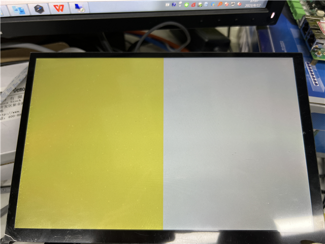
From the above figure, it can be seen that half of the screen displays yellow and the other half displays gray. This is abnormal, as the normal display should show the entire screen in gray.
What is causing this error display? Looking forward to your answer.
Regards,
Li