This thread has been locked.

If you have a related question, please click the "Ask a related question" button in the top right corner. The newly created question will be automatically linked to this question.

upp problem


u32 upp_buffer_xmit[1024],upp_buffer_rcv[1024];

void upp_test(void)

{

int upp_error_count = 0;

int i,size;

for (i = 0; i < 1024; i++)  ==>> for(i = 0; i < 2048; i++)

{

        upp_buffer_xmit[i] =0x55AAFFBB;

upp_buffer_rcv[i] = 0;

}

  while(UPP_UPQS2_ADDR & 0x00000002 == 1) {};

    UPP_UPQD0_ADDR = (unsigned int)&upp_buffer_rcv[0]; 

    UPP_UPQD1_ADDR = (0x0001 << 16) | 0x10000; 

    UPP_UPQD2_ADDR = 0x10000;


  while(UPP_UPIS2_ADDR & 0x00000002 == 1) {};

  UPP_UPID0_ADDR = (unsigned int)&upp_buffer_xmit[0]; 

  UPP_UPID1_ADDR = (0x0001 << 16) | 0x10000; 

  UPP_UPID2_ADDR = 0x10000;


for(i = 0; i < 1024; i++)

{

if(upp_buffer_xmit[i] != upp_buffer_rcv[i])

{

printf(" %d : 0x%x,0x%x\n",i,upp_buffer_xmit[i],upp_buffer_rcv[i]);

upp_error_count++;

}

}


if (upp_error_count)

printf("uPP transfers completed with %d errors.\n", upp_error_count);

else

printf ("uPP transfers complete with no error!\n");

}


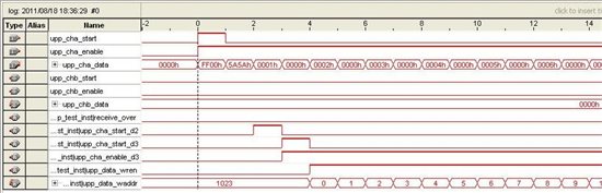
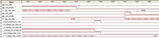
This is my test code, A2B DLB mode,transfer error.upp_buffer_rcv[1024] didn't receive any data,is still fill with 0.

but if I change the Buffer initial circle code,e.g for(i = 0; i < 2048; i++),which show in red color,transfer ok and upp_buffer_rcv[1024] fill with 0x55AAFFBB.

then i change to for(i = 0; i < 1500; i++), before 476(1500-1024) of the upp_buffer_rcv[1024] is fill with 0x55AAFFBB,but after 476 is fill with 0.

so I thought the DMA transfered data which is just after upp_buffer_xmit[1024],  why do this happen?

absolutely,initial circle with for(i = 0; i < 1500; i++) which exceed the array range is wrong.


  • One thing that I notice about your code is that you begin checking the buffer contents immediately after programming the transmit operation.  I recommend waiting until after the EOW event is triggered by the receive channel.  At that time, you can be confident that the transfer is complete and the data is ready to compare.

    Hope this helps.

  • just as you said, the EOW event is not triggered,I watch for the UPICR regester and other registers,the result is worse.as follows:

    &upp_buffer_xmit = 0xc0fa1c00,&upp_buffer_rcv = 0xc0fa2008

    before trasfer: 

     UPIER=0x0, IS0 = 0x0, IS1 = 0x10000,IS2 = 0x40

     QS0 = 0x0, QS1 = 0x10000, QS2 = 0x40

     QD0 = 0x0, QD1 = 0x0, QD2 = 0x0

     ID0 = 0x0, ID1 = 0x0, ID2 = 0x0


    after transfer : 

     UPIER=0x0,  IS0 = 0x0, IS1 = 0x10000,IS2 = 0x40

     QS0 = 0x400, QS1 = 0x20000, QS2 = 0x40

     QD0 = 0xc0fa2008, QD1 = 0x10400, QD2 = 0x

     ID0 = 0xc0fa1c00, ID1 = 0x10400, ID2 = 0x400


    It seems the transfer process hasn't established, the clock of the upp is ok.and the initial process is followed the User's Guide step by step, someone who can provide the registers'  initial values? such as UPTCR,UPICR,...and my initial value is :

    void test_upp_init(void)

    {

    unsigned int i;

    //reset uPP

        SETBIT(UPP_UPPCR_ADDR, UPP_UPPCR_SWRST);

        for(i = 0; i < 300; i++) {}; //wait 200 clock cycles for reset.

    CLRBIT(UPP_UPPCR_ADDR, UPP_UPPCR_SWRST);  

       //setup control registers

    UPP_UPCTL_ADDR=(0x3 << 0) | (0x1 << 2) | (0x0 << 3) | (0x0 << 4) | (0x0 << 16) | (0x01 << 17) | (0x0 << 18) | (0x0 << 21) | (0x0 << 24) | (0x1 << 25) | (0x0 << 26) | (0x0 << 29);

    UPP_UPICR_ADDR=(0x01 << 29) | (0x1 << 20) | (0x1 << 19) | (0x1 << 13) | ( 0x0 << 8) ;

    UPP_UPTCR_ADDR= (0x1 << 0) | (0x1<<8)|(0x0<<16)|(0x0<<24);

    UPP_UPIVR_ADDR = 0x0;

    UPP_UPDLB_ADDR = (0x1 << 12);

    UPP_UPIEC_ADDR = UPP_INT_ALL_CLEAR;

    UPP_UPIES_ADDR |= 0x00000c0c; 

    UPP_UPPCR_ADDR=0x00000008;

    }

  • Actually, I've noticed another problem with your transfer parameters.  You are setting the UPxD1 registers to:

    (1 << 16) | 0x10000

    This is a problem since both operands of the OR operation are equal to each other.  You could achieve the same results by just assigning the following value:

    1 << 16

    Basically, you are telling the uPP peripheral that your lines have 0 size, so the transfer probably never happens.  I recommend changing your assignment to this:

    (1 << 16) | 4096

    This will match the size of your data buffers (i.e. 1024 4-byte integers).

    Hope this helps.

  •  

    I have tried just as you say, and change the UPPCR register value to 0x09, the test result is changed:

     num: A , B

     0 : 0x0,0xeff0eff

     1 : 0x1,0xeff0eff

     2 : 0x2,0xeff0eff

     3 : 0x3,0xeff0eff

     4 : 0x4,0xeff0eff

     5 : 0x5,0xeff0eff

     6 : 0x6,0xeff0eff

     7 : 0x7,0xeff0eff

     8 : 0x8,0xeff0eff

     9 : 0x9,0xeff0eff

     10 : 0xa,0xeff0eff

     11 : 0xb,0xeff0eff

     12 : 0xc,0xeff0eff

     13 : 0xd,0x0

     14 : 0xe,0x1

     15 : 0xf,0x2

     16 : 0x10,0x3

     17 : 0x11,0x4

     18 : 0x12,0x5

     19 : 0x13,0x6

     20 : 0x14,0x7

     21 : 0x15,0x8

     22 : 0x16,0x9

     23 : 0x17,0xa

     24 : 0x18,0xb

     25 : 0x19,0xc

     26 : 0x1a,0xd

     27 : 0x1b,0xe

     28 : 0x1c,0xf

     29 : 0x1d,0x10

    ....

    The EOW has trigged,I don't know why B buffer's first 12 integer is 0xeff0eff, even though I changed the DMA channel initial sequence.

    the interesting thing is: when I change the xmit && rcv buffers from 'int' to 'char' mode,the 0xeff0efff numbers reduced to 6

  • Have you changed your buffer initialization?  Based on the code from your first post, I would have expected the transmit buffer to be filled with 0x55AAFFBB values.

    Also, I think that your UPICR value is suspect.  If the combined register value is really 0x9, then the channels are probably not configured properly to interact with each other.  Since channel A is operating in transmit mode, STARTA has no effect.  However, by setting STARTB and ENAB to 0, you are telling the receive channel not to wait until the transmitter actually starts sending data.  This could explain why your receive buffer has several "bad" values at the beginning.  Also, setting STARTPOLA and STARTPOLB to different values could have undesirable results.  I recommend the following settings for UPICR:

    • ENAB = 1
    • STARTB = 1
    • All other fields = 0

    Hope this helps.

  • now I debug the upp with FPGA, upp transfer 2k data to FPGA,then feedback to upp.the FPGA signals seems right,but the upp receive a bad data at the beginning,all other data(s) are right. Incording to the diagram, the first data I should receive is 0x5A5AFF00,but is 0 instead.