This thread has been locked.

If you have a related question, please click the "Ask a related question" button in the top right corner. The newly created question will be automatically linked to this question.

SK-AM62: A53 and M4 / R5 Hybrid Communication Verification

Part Number: SK-AM62

Verification for A53 and M4 / R5 Hybrid Communication Verification

1. Development environment with CCS has already been established.


2. Reading RTOS/NO-RTOS [MCU+ SDK] documentation.
M4/R5 seems somewhat similar yet different. Are there more formal documentation or information available to understand the differences or usage scenarios?
It seems the same from the CCS samples.

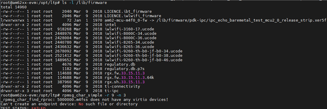
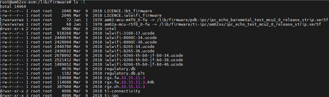
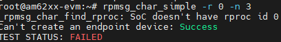
3. Does A53 require loading a specific DTS file (Processor SDK Linux for AM62x09_00_00_03)? Or is there a need for any modifications?


RTOS/NO-RTOS [MCU+ SDK] seems to focus more on the MCU, and it appears that Processor SDK Linux for AM62x doesn't provide much explanation in this regard.

  • Hi Vic,


    These two pages on Linux Academy for AM62x answers your questions:

    Booting Remote Cores: https://dev.ti.com/tirex/explore/node?node=A__AISILbMWZ4d84U2oSmXcdA__linux_academy_am62x__XaWts8R__LATEST

    IPC Example: https://dev.ti.com/tirex/explore/node?node=A__ACKtJpWz8b53RwT-PJ4qmA__linux_academy_am62x__XaWts8R__LATEST


    Does A53 require loading a specific DTS file (Processor SDK Linux for AM62x09_00_00_03)? Or is there a need for any modifications?

    Answer: The Linux device tree include information about which firmware to load into the remote cores. "Booting Remote Cores" page linked earlier provides more details.


    Are there more formal documentation or information available to understand the differences or usage scenarios?

    Question:  Are there more formal documentation or information available to understand the differences or usage scenarios?

    Answer: I suggest you start with the two pages above. 

    Please, let me know of any clarifying questions after you have ran the out of box demos. 


    Best regards,


    Qutaiba

  • Hi Qutaiba

    Thank you for providing information and guidance.

  • Hi Qutaiba

    The SDK version I am using is Processor SDK Linux for AM62x09_00_00_03. I am using a ompiled version of the image.

    May I ask if ipc_echo_baremetal_test_mcu2_0_release_strip.xer5f was generated through Code Composer Studio?

    Is it possible to modify the functionality of the M4F Core arbitrarily when booting Remote Cores?

    Booting Remote Conterl:

    IPC Example:

  • Hi Vic,


    Before starting the remote core, you have to link the appropriate firmware. See this example:

    root@am62axx-evm:~# cd /lib/firmware/

    root@am62axx-evm:/lib/firmware# ln -sf /lib/firmware/ti-ipc/am62axx/ipc_echo_test_mcu2_0_release_strip.xer5f am62a-mcu-r5f0_0-fw


    Note that it is important to CD to /lib/firmware when you link the firmware.


    Then reboot the EVM and then run the remote core:


    root@am62xx-evm:~# echo start > /sys/class/remoteproc/remoteproc0/state


    Then try the already compiled IPC example:

    root@am62axx-evm:/opt/edgeai-gst-apps# rpmsg_char_simple -r 0 -n 3

    Created endpt device rpmsg-char-0-1502, fd = 4 port = 1025

    Exchanging 3 messages with rpmsg device ti.ipc4.ping-pong on rproc id 0 ...


    Sending message #0: hello there 0!

    Receiving message #0: hello there 0!

    Sending message #1: hello there 1!

    Receiving message #1: hello there 1!

    Sending message #2: hello there 2!

    Receiving message #2: hello there 2!


    Best regards,


    Qutaiba

  • Hi Qutaiba 

    I Provided a screenshot of my running results.

    Before starting the remote core, you have to link the appropriate firmware. See this example:

    root@am62axx-evm:~# cd /lib/firmware/

    root@am62axx-evm:/lib/firmware# ln -sf /lib/firmware/ti-ipc/am62axx/ipc_echo_test_mcu2_0_release_strip.xer5f am62a-mcu-r5f0_0-fw

    Provide running photos:


    Note that it is important to CD to /lib/firmware when you link the firmware.


    Then reboot the EVM and then run the remote core:


    root@am62xx-evm:~# echo start > /sys/class/remoteproc/remoteproc0/state

    Provide running photos:


    Then try the already compiled IPC example:

    root@am62axx-evm:/opt/edgeai-gst-apps# rpmsg_char_simple -r 0 -n 3

    Created endpt device rpmsg-char-0-1502, fd = 4 port = 1025

    Exchanging 3 messages with rpmsg device ti.ipc4.ping-pong on rproc id 0 ...

    Provide running photos:

    Sending message #0: hello there 0!

    Receiving message #0: hello there 0!

    Sending message #1: hello there 1!

    Receiving message #1: hello there 1!

    Sending message #2: hello there 2!

    Receiving message #2: hello there 2!

  • HI Qutaiba Saleh

    The issue has been fixed.
    I am currently in the process of verifying it in Code Composer Studio Debug.
    As shown in the screenshot, Trace Debug M4F requires the TaskP_freertos.c file. I have checked the SDK installation directory and couldn't find this file.


    Currently, we are discussing two possible approaches:
    1. Verification of Trace Debug M4F in the Code Composer Studio development environment for I/O.
    2. Debugging the collaboration between A53 and M4F.

    Can't find a source file at "/home/gtbldadm/nightlybuilds/repo_manifests/scripts/jenkins/mcu_plus_sdk_am62x_09_00_00_19/source/kernel/freertos/dpl/common/TaskP_freertos.c" 

  • HI Qutaiba Saleh

    The issue has been fixed.

    Can I ask a question about AM62, which has Cortex A53 + Cortex M4F + Cortex R5? In terms of mixed development and applications, how many experimental and development approaches are possible?

    1. Using a general TI Cortex M4F MCU for peripheral I/O and functional verification, then porting it to AM62 for validation.
    2. Due to the uniqueness of the chip, is development required in the AM62 BSP environment?

    Is Cortex R5 also developed similarly to Cortex M4F? I've read about the boot process and stages, but the question is about application and use after the system runtime.

  • Hello  Vic,

    Can I ask a question about AM62, which has Cortex A53 + Cortex M4F + Cortex R5? In terms of mixed development and applications, how many experimental and development approaches are possible?

    In AM62X devices, the software package is divided into two packages: one is the processor SDK and the other is the MCU+SDK.

    The processor SDK mostly belongs to Linux, and you can experiment on the A53 core.

    MCU+SDK belongs to RTOS/NO RTOS, and you can experiment on R5F and M4F cores.

    2. Due to the uniqueness of the chip, is development required in the AM62 BSP environment?

    For this question, we should get a reply from Linux experts.

    Is Cortex R5 also developed similarly to Cortex M4F? I've read about the boot process and stages, but the question is about application and use after the system runtime.

    The AM62X R5F core can be used for DM (device management) operations like reset, power management, and application purposes. You can use the

    R5F  core on the application side similar to M4F ; there is no problem, but when you use the R5F on the application side, sleep modes do not support. Can

    you  please check the  below link for more details?

    https://software-dl.ti.com/mcu-plus-sdk/esd/AM62X/latest/exports/docs/api_guide_am62x/DEVELOP_AND_DEBUG_DMR5.html

    1. Using a general TI Cortex M4F MCU for peripheral I/O and functional verification, then porting it to AM62 for validation.

    I understood that you have already verified M4F applications in other MCUs and are trying to port them to the AM62X MCU.

    You can do it. There is no problem integrating and testing them easily, and most likely you need to integrate your old application into the AM62X M4F and

    not drivers. This process can be done easily. May I know what peripherals you are using on M4F so that I can better assist you?

    Regards,

    S.Anil.

  • 2. Due to the uniqueness of the chip, is development required in the AM62 BSP environment?

    For this question, we should get a reply from Linux experts.

    Hi Vic Chang,

    TI provides a BSP (Board Support Package) as part of it's SDKs. The Processor SDK for LInux and the MCU+ SDK mentioned in the thread above provide a group of drivers written and adapted to the individual cores (A53, M4, R5) and peripheral IP blocks that provide a Hardware Abstraction Layer for the software that goes above it, whether that be an application (No RTOS), FreeRTOS RTOS, or Linux (A53). These drivers, along with a bootloader (U-Boot for Linux in most cases for AM62x) and other configuration/start up code wrapped up together to form a BSP.

    So, to directly answer your question "is development required in the AM62x BSP environment", yes and no. TI provides a set of drivers validated and tested on several development platforms like the AM62x Starter Kit. So, a BSP for this board is provided and you can use it for development on that board. Included in this is drivers fro the SoC peripherals on the AM62x (UART, I2C, Ethernet, etc.), and drivers for the external components on the board (Ethernet Phys, I2C extenders, EEMC, etc.). So, for the most part, this board has a complete BSP and no further development is really needed. This is the "no" part of the answer to your question. TI provides drivers for the SoC and for the boards that they provide. A good summary of this can be seen on the Software Build Sheet.

    The great thing about the embedded space is that developers go build their own boards. If they choose the exact same components as a TI board, then the drivers would exist. If they choose different components, drivers may or may not exist. One of the powerful aspects of Linux and open source software is that many drivers exist for components and these drivers can likely be used with the TI SDK in a custom Linux distribution. Choosing board components with drivers available will reduce/eliminate the BSP effort. If components are chosen that do not have good open source support, driver development wil be needed to fill that gap, but it will likely still be able to utililize the underlying SoC drivers provided by TI. So, BSP development is required, but assisted by the TI software offering of SoC enablement. This is the yes or maybe part of your question.

    Sorry if this is a bit lengthy, but I wanted to try to be as clear as possible. I hope this is helpful to you.

    Thanks,

    Ron

  • HI   Swargam Anil

    Thank you for providing discussion topics and responses. Due to the heterogeneous multi-core architecture of AM62, I've reviewed the architectures of many vendors, and in fact, TI's architecture is complete and impressive. So, in terms of the specific details of the questions, I will have many assumptions about development methods, and with different expertise, I would like to find the most efficient way. In designing the product, I hope to make use of all the features and limits of this product.

    Conclusion:
    I'm presenting my understanding and thoughts for synchronization.
    Functional Summary:
    1. Low power management is mainly done by the R5 Core.
    2. The M4 primarily handles real-time I/O.
    M4/R5 can also execute general application development.
    The R5F core can be used for Device Management (DM) operations, similar to the M4F core. However, when using the R5F core for application purposes, it does not support sleep mode.

    Here are my goals:
    M4 handles peripheral I/O control and communication.
    R5 operates in Low Power Mode.

    I have a few questions for discussion:
    1. Sleep/Wake-Up in Low Power Mode.
    2. AM62x SK EVM User's Guide, page 58, mentions the FT4332 UART to USB Bridge. Is this UART used for R5 Wake-Up? Are the other MCU Headers all related to M4F?

    AM62x Low-Power SK EVM User’s Guide

  • Hello Vic,

    in fact, TI's architecture is complete and impressive. So, in terms of the specific details of the questions, I will have many

    I'm really glad to hear that, and thanks.

    I'm presenting my understanding and thoughts for synchronization.
    Functional Summary:
    1. Low power management is mainly done by the R5 Core.
    2. The M4 primarily handles real-time I/O.
    M4/R5 can also execute general application development.
    The R5F core can be used for Device Management (DM) operations, similar to the M4F core. However, when using the R5F core for application purposes, it does not support sleep mode.

    Yes, your understanding is correct, and adding the below points will give a clear picture of the AM62X architecture.

    You can use the A53 core for peripherals and real-time IO applications as well.

    One more thing is that the AM62X has two M4F cores: one dedicated for application purposes and another for security applications.

    Here are my goals:
    M4 handles peripheral I/O control and communication.
    R5 operates in Low Power Mode.

    You can use R5F in low-power mode, and may I know which type of applications you are planning to run on R5F?

    Running general periperhals like GPIO UART SPI I2C there is no problem and you can achieve low power mode.

    We need more details about your R5F application so that we can suggest you get the R5F in low power mode.

    See the below image. WKUP_UART0 is used in the USB to UART bridge, and please try to download the HW schematic of the AM62X and check more

    details about headers, which are the pins are going to headers. I will share FAQ shortly .

    I am really curious to know what type of application will you planning to run on AM62X devices.

    Reagrds,

    S.Anil.

  • HI  Swargam Anil

    Thank you for being open to discussing challenges in a challenging manner. I believe that the TI platform can rise to the challenge due to its comprehensive hardware and software architecture. The professionalism of TI's partners also enables in-depth discussions on both the limits and details of the platform.

    I hope to gain a deep understanding of the usage and limitations of each core. This will be essential for effectively expanding the software architecture and customizing hardware circuit designs before finalizing the design.

    The primary focus is on applications related to autonomous driving, including power efficiency, multi-core cooperation, and adjustments for various scenarios and environments.

    Provided the responsibilities of each core, so we can discuss with sufficient information and ideas.

    1. R5 Core: (Standby Environment A53 S3 Mode Suspend-to-RAM)

    Its main role is to achieve low-power external I/O wake-up, specifically WKUP_UART0.

    2. M4 Core: (Real-time Cooperative Computing with A53 IPC M4F)

    It handles real-time data algorithm processing for UART, GPIO, CAM, I2C, and SPI.

    Common issues related to microcontroller cores:
    1. Is there only one set of MCU Header for sharing between M4 and R5 cores?
    2. Do A53 cores use the same storage space for storing the Config File?

    As for the security mode core, it may not be my primary focus, but Can provide additional data (It is Ok!).

  • Hello Vic,

    I have seen your queries and will provide a reply by tomorrow, as today I am fixing other issues.

    Sorry for the inconvenience.

    Regards,

    S.Anil.

  • HI  Swargam Anil

    Thank you for your professional service and your willingness to engage in in-depth discussions
    With me on system architecture, software, hardware, and related confirmations.

    I greatly appreciate your assistance

  • Hello Vic,

    You will get a reply in another 1 or 2 hours.

    Regards,

    S.Anil.

  • HI  Swargam Anil

    No worries, don't rush it.
    After all, this is a matter of exploring a possibility.
    I believe we can discuss the possibilities based on the available information.

  • Thank you for being open to discussing challenges in a challenging manner. I believe that the TI platform can rise to the challenge due to its comprehensive hardware and software architecture. The professionalism of TI's partners also enables in-depth discussions on both the limits and details of the platform.

    Hello Vic,

    TI can support both the limits of HW and SW. So, if you have any query on HW, you can raise a new thread so that HW experts will take care of it.

    This e2e can be support in both HW and SW queries .

    The primary focus is on applications related to autonomous driving, including power efficiency, multi-core cooperation, and adjustments for various scenarios and environments.

    Thanks for sharing end-product details. This device can be fit in to achieve your requirements.

    Its main role is to achieve low-power external I/O wake-up, specifically WKUP_UART0.

    Based on the above information, you are mostly running the UART application and controlling GPIO's on R5F .So, you can able to get low power .

    2. M4 Core: (Real-time Cooperative Computing with A53 IPC M4F)

    The M4F core has less memory, runs at 400 MHz, and does not have cache . And processing. Real-time algorithms for UART, GPIO, I2C, SPI,SPI and

    CAN data There is no problem to use M4F .

    But if you are trying to process images and other big algorithm where you need more more memory , then just move to the A53 core.

    I understand that you are trying to implement AUTOSAR on the M4F core.

    Can you please confirm where you wanted to use AUTOSAR on which core?

    1. Is there only one set of MCU Header for sharing between M4 and R5 cores?

    There are J3, J9, J10, and J17 connectors available on HW. See what pins are going to them.

    You can download design package files from the below link. So, in that folder, you will have a schematic of AM62X.

    Please use the FAQ for more details about AM62X Hw.

    https://e2e.ti.com/support/processors-group/processors/f/processors-forum/1276282/faq-am625-am623-am625-q1-am62a7-custom-board-hardware-design-information-related-to-the-processor-evaluation-modules-or-starter-kits

    2. Do A53 cores use the same storage space for storing the Config File?

    I understand that for the above question, you wanted to store some config files on A53 memory ?

    Regards,

    S.Anil.

  • HI  Swargam Anil

    Thank you for your assistance and response.

    Can you please confirm where you wanted to use AUTOSAR on which core?

    The design will primarily focus on M4, and R5 will be designed for low-power external interrupts (with no computational design).

    I understand that for the above question, you wanted to store some config files on A53 memory ?

    This issue in more detail, currently, A53 can remotely update the image files of M4. In some heterogeneous multi-core designs by manufacturers, A53 and M4 share the same storage space.

    Is the storage space for A53 and M4 separate? Because, for M4, I hope to be able to update some binary verification files.

  • Hello Vic,

    The design will primarily focus on M4, and R5 will be designed for low-power external interrupts (with no computational design).

    We don't recommend using AUTOSAR on the M4F core since it does not have more memory and cache.

    When you integrate AUTOSAR packages, you may need more memory space. Please keep it in mind when you use AUTOSAR on the M4F core.

    I am assuming that you are not using AUTOSAR architecture on your project, and if you don't use it, please go use general peripherals on the M4F core.

    Is the storage space for A53 and M4 separate? Because, for M4, I hope to be able to update some binary verification files.

    Actually, the A53 core is running on DDR memory, and the M4F core is running on IRAM and DRAM memory. So, both cores are using two different

    memories.

    Regards,

    S.Anil.

  • HI  Swargam Anil

    Thank you for your professional response.

    Nice to meet you.