This thread has been locked.

If you have a related question, please click the "Ask a related question" button in the top right corner. The newly created question will be automatically linked to this question.

Power Supply for the C6670

Other Parts Discussed in Thread: UCD9222, UCD7242

Hi, all:

Now, I am using the C6670 for design. And I am puzzled by the Power Supply of the C6670. From the TI's reference design guide, I know the UCD9222+UCD7242 should be used to provide the C6670's Core Power supply. I have some question about the 6670L schematic on Page 33.

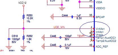
Question 1#: The Pin 4 of the UCD9222 have a voltage( about 1.5v: 12v * (1.5k/(10.2k+1.5k))), The voltage we need for the 6670 core is 1.0v. How this voltage used for?

Question 2#:UCD9222 have multiple interface such as: JTAG, PMB, VID. From this Forum I know that the UCD9222 should be configured before it work rightly. Can each of these three interface be used to perform configuration?

If we use JTAG and PMB interface, where to buy the link cable and how much?

  • Pin 4 of the UCD9222 is the VinMON pin.  This pin is connected to a 12-bit ADC which allows the device to monitor the input voltage for the device.  The 12-bit ACD is limited to a dynamic range of 0 to 2.5V so an external resistor divider is required to limit the input voltage range at the VinMON pin.  The scaling of the voltage is then defined in the part using the VIN_SCALE_MONITOR command.  Once this is done the device can monitor the input voltage which is used in a number of alerts. 


    Only the PMBus is used to program the UCD9222.  This is accomplished using two items.  

    The first is the Fusion Digital Power Designer utility available on TI.COM at no cost.  This software tool is used to design you power supply system, program the registers in the UCD9222 and monitor the performance of your design.  Note that the power supply design for the EVM is based on the passive components purchased for that board.  Unless you are specifying these exact components you should use the Fusion software to enter the specifications of the passives you have selected to ensure that they will work properly.  

    The second is the TI USB Interface Adapter Evaluation Module.  This USB-to-GPIO module is used by the Fusion software to communicate with the UCD9222.  It is available for purchase from both TI.COM and from distributors.  Note that the PMBus is a two pin serial interface and that only the PMBus_CLK and PMBus_Data pins are used to communicate with the Fusion software. A three pin connector with CLK, DATA and Ground are all that's needed to program the part.

  • "The first is the Fusion Digital Power Designer utility available on TI.COM at no cost.  This software tool is used to design you power supply system, program the registers in the UCD9222 and monitor the performance of your design.  Note that the power supply design for the EVM is based on the passive components purchased for that board.  Unless you are specifying these exact components you should use the Fusion software to enter the specifications of the passives you have selected to ensure that they will work properly."

    I download the  Fusion Digital Power Designer and install it, when run it, an information said no USB cable find. Which USB cable is need while use it?


  • You need the TI USB Interface Adapter Evaluation Module.  This USB-to-GPIO module is used by the Fusion software to communicate with the UCD9222.  It is available for purchase from both TI.COM and from distributors. 

  • i have down load fusion_digital_power_designer,and config the UCD9222,The USB ADAPTOR work right.,and project can be saved as a .xml file.

    but I do not know how to download it to the UCD9222 device,could you help me? my email :          804842015@qq.com

  • Hi ,

    Through the USB to GPIO pod provided by TI, the user can trace and configure the parameters in UCD9222 with the

    Smart-Fusion GUI. Please refer board TRM section "3.2.10 PMBUS1, PMBUS Connector for Smart-Reflex Control" for more information from below link.

    You can post your follow up queries on Digital power forum for faster and appropriate response.

    Thank you.

  • Hi Xiang,

    Once you have set the configuration in the Fusion Digital Power Designer software, you should see the 'write to hardware' button in the configure tab on the left side of the window. That button will write your configuration to the device. See section 6.1 of the Fusion Digital Designer User's Guide.

    Regards,

    Bill