This thread has been locked.

If you have a related question, please click the "Ask a related question" button in the top right corner. The newly created question will be automatically linked to this question.

4 interrupts for each GPIO rising edge?

Anonymous
Anonymous
Other Parts Discussed in Thread: STRIKE


Hi,


I would like to ask some questions on GPIO interrupt on DM6437.


I have a regular ISR which I configured to be triggered by the rising edge of GP[12]. There related code snippet is:


GPIO_DIR01= 0x00001000;          //GP[12] direction as input

GPIO_BINTEN |= 1;//Enable bank0


GPIO_SET_RIS_TRIG01=0x00001000;//Enable rising edge interrupt detection

GPIO_CLR_FAL_TRIG01=0x00001000;//Disable falling edge interrupt detection


CSR |= 1;

IER = 0x00000000

              | (1<<1)          // set INT5 and NMIE                

              | (1<<5)

            ;

INTC_INTMUX1= 0x00004800;//GP[12] has no direct interrupt; it must use GPIO Bank

              0 interrupt number 72


And of course, there is an vector interrupt service table which associates the ISR function with the interrupt.


I have already reported one discrepancy between sprs345d and the actual measurement in GP[12] is IPU, not IPD: manual mistake? : GP[12] seems to have IPU rather than IPD.


Since GP[12] is high when unconnected, I uses a 0V signal to trigger it. Ideally:

1.    When 0V pin touches GP[12], there is a falling edge since GP[12]'s input pin has its connected voltage transitioned from IPU to 0.

2.    When 0V pin leaves GP[12], there is a rising edge corresponding to the effect of IPU, which would trigger an interrupt.

Therefore, there will be a total of 1 interrupt for a touch-then-leave action.


But my problem is that I have detected 4 interrupts rather than 1.

1.    Two at "touch".

2.    Two at "leave".


I have used a variety of mechanism to confirm my observation, including both static counter in ISR as well as LED lights on the board. I definitely get 4 interrupts for each "touch-then-leave".


I googled ti.com and there are two articles containing some information on configuring GPIO interrupt, among which the second is particularly relevant:

1.    Configuring GPIO Interrupts

2.    Avoiding Double Interrupts with the GPIO Peripheral


However, (2) suggests not enabling bank interrupt and pin interrupt  at the same time for pins having their own direct interrupts, and this is exactly what I have done in the code snippet above: not using direct interrupt at all and only uses bank0's interrupt for GP[12]. Therefore I have already followed the guidelines there.


It is quite strange then for me to get this quadruple interrupts for a single "touch-leave" action. Especially for "touch", there is no rising edge and why I am still getting interrupts, and executed twice? For "leave", I expected once, not twice.


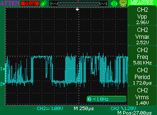
I also thought it possible to finally pinning down the cause to the rapidly changing transient voltage during the "touch-then-leave". I in fact did it in a quite reliable manner: GP[12] is connected to a hole on a high-quality breadboard, and then plug (touch) the 0V pin to another hole which is connected with the GP[12] hole on the breadboard, and unplug it after some time, both in an unhesitated manner. Nonetheless, I still observed rapidly oscillating transient waveform captured by oscilloscope in these two short intervals. The picture above is what happens when "leave", i.e., GP[12] being pulled back to high by its internal IPU. There is a strikingly large number of rising and falling in these short period.


So my questions are:


1.    Why do I get 4 interrupts for each "touch-then-leave"? Why two even when there is no rising edge ("touch") when I configured only rising edge? Why two at "leave"?


2.    Do they relate to the rapidly changing transient voltage? How frequently (in clock cycles) does GPIO interrupt module samples pin value? Please note that each grid in my oscilloscope is 250µs.


3.    If it is due to the rapidly changing transient voltage that quadruple interrupts arises, how should I do to avoid it? In a product there must be buttons, and they are implemented using switches. As long as switches exist, there might exist the same short-time transient voltage as with my "touch-and-leave". Quadruple interrupts would make the buttons unusable. Therefore, what is the solution?


I of course can use time triggered interrupts to sample GPIO input pin value as an alternative way of implementing GPIO input interrupt, but this wastes  timer resources. I could also write overhead statements in ISR to reduce 4 interrupts to 1 for each "touch-then-leave", but without knowing the underlying cause of the issue this approach is subjected to hidden problems. For these reasons, I believe the cause for this problem needs to be thoroughly investigated.


Zheng


  • You have discovered the annoying problem known as switch "bounce."  The noisy scope plot you are seeing is typical, and will be especially bad for touching a wire to a breadboard.  You can either deal with the problem through hardware (circuits that debounce the switch signal before it reaches your processor) or software (various tricks like polling or delaying re-enable of interrupts to compensate for the known noisy switch signal).

  • Anonymous
    0 Anonymous in reply to MattLipsey

    Matt,


    Question on keyboard:


    So do you mean GPIO's interrupt triggering ability is too sensitive here for my "breadboard button" use? And the common theme of both the hardware and software fix you suggested is to somehow delay the voltage detection or some sort of rectification (might not be a proper term here), with the purpose of capturing only one interrupt within a certain frame of time?


    I am interested in knowing on common devices how is switch "bounce" handled, for example on a PC or Arcade Game machine? Does there exist the debounce circuit as you have mentioned?


    while (1)

    {

                switch(buffer)

                {

                            case "a":

                            ...

                            break;


                            case "b":

                            ...

                            break;


                            case "c":

                            ...

                            break;

                            ...

                }

    }


    I also have impression on code on some operating system books, and they generally contain an infinite while loop(see above) which is responsible for calling  functions depending on the value of a keystroke buffer. This is to say, the infinite while loop polls the keystroke buffer continuously and responds accordingly. So on the software level, this is simply polling.


    But does there exist debouncing circuit between the keyboard and the keystroke buffer? Equivalently, does there exist an external, or controller internal to the processor which could be called a "keyboard controller", the functionality of which includes:

    1.    debouncing

    2.    bufferintg


    Does this exist on common desktop devices? If not, how are keyboard input handled? Simply using software to implement "delaying re-enable of interrupts"?


    Question on GPIO:


    The sensitivity of GPIO's interrupt triggering as manifested by the switch "bounce" here made it hardly directly usable as buttons/keyboard. Why are they made so sensitive? TI has been making chips for decades and I am sure they have numerous user cases of using keyboard, so why hasn't GPIO been improved or tuned to better suit button switch?


    On the other hand, I could also have a realization on why GPIO samples data that fast. I used GPIO to implement SCCB protocol to communicate with OV sensor. SCCB's speed is100k cycles/s, so each period is only 10µs. In order for GPIO pin in input state to read out OV sensor registers successfully, it must be able to log at least one voltage change within a period's 10µs, so the requirement here is that it must be fast enough to be usable in communication with other devices.


    Therefore we have two competing requirements: For GPIO to implement digital protocols, it must be fast/sensitive enough; for implementing keyboard, it needs to be slow. These two requirements differ wildly like the two ends of a pole. For example, even a professional typewriter does not press buttons ten times a second, so the sample period might be as low as 100ms; however for digital protocols we see the it must be able to detect voltage change in 10µs. Referring back to my oscilloscope wave image above, we see that each period is 250µs, and there are over a dozen periods (12×250 = 3000µs = 3ms) for the a single breadboard voltage rise or fall, and 3000µs is sufficient for 300 GPIO voltage samples if the minimum response time is 10µs, so it is then not surprising to see multiple interrupts triggered for a single breadboard "touch" or "leave", and quite fortunately actually not hundreds of interrupts.


    So the finally decision of the circuit designer is to make GPIO fast. A fast GPIO can be made versatile as to support low sampling rate using software delay / interrupt disable-reenable, but there is no way to make a slow GPIO work fast using software instructions.


    So does the reasoning here stand?


    Zheng

  • I think the general rule is that these chips have been designed to retain as much flexibility as possible because they are used in a wide variety of applications.  It is then up to the designer to know how to apply knowledge of electronic design and software to come up with a system that meets their requirements while balancing cost & performance.

  • Anonymous
    0 Anonymous in reply to MattLipsey


    Matt,


    This problem is resolved. Thanks very much.


    Zheng


  • Zheng,

    How did you solve this problem? This is a really big problem.

    Thank you,

    Igor

  • Anonymous
    0 Anonymous in reply to Igor

    Igor,


    Use a while loop polling rather than GPIO interrupt.


    Even for professional typewriter or game players, the speed they strike keyboard do not exceed 10/strikes per second. So for normal operation, I assume it is same to poll each key's voltage status every 100ms, and you use this to determine if a key has been pressed down or not.


    GPIO interrupt detection is too sensitive and is not intended for this purpose.


    Zheng


  • Zheng,

    Thank you for your quick answer.

     It is very surprising that TI does not endorsethe use of a keyboard or buttons.

    Igor

  • Anonymous
    0 Anonymous in reply to Igor

    Igor,

    Please read the answer above from MattLipsey on "debounce circuit". I believe these are external circuits which generally are not included inside the chip.


    Zheng

  • Zheng,

    thank you VERY MUCH,

    Now I can colve this problem.

    Igor.

  • Anonymous
    0 Anonymous in reply to MattLipsey

    Matt,

    Which of the two methods (debouncing circuit & software tricks) is more common on real products?

    And for debouncing circuit, is there any cheap integrated solution (like a very small chip), or the circuit has to be built from elemental components (resistor, capacitor, transistor, etc.)?


    Zheng

  • Hi,

    sorry for replying as question but actually i need some help

    When i run my 6446EVM booting from flash to run the demo as standalone i get the interfcae screen but when i choose any demo using the ir-remote i get nothing happen i can choose any demo but when i press play the screen go to black for a part of second and return back to its state that shows the player keys without happen any thing

    my 6446EVM starting output is as follow there is some errors on it i mark it in yellow please ana one can help me

    DM644x initialization passed!
    TI UBL Version: 1.50
    Booting Catalog Boot Loader
    BootMode = NOR
    Starting NOR Copy...
    CFI Query...passed.
    NOR Initialization:
            Command Set: Intel
            Manufacturer: INTEL
            Size: 0x00000010 MB
       DONE
    Jumping to entry point at 0x81080000.


    U-Boot 1.2.0 (May 20 2009 - 01:04:51)

    I2C:   ready
    DRAM:  256 MB
    INTEL Flash: 16 MB
    In:    serial
    Out:   serial
    Err:   serial
    ARM Clock :- 297MHz
    DDR Clock :- 162MHz
    MSP430 Firmware supports AM/PM Feature
    Hit any key to stop autoboot:  0
    ## Booting image at 02060000 ...
       Image Name:   Linux-2.6.18_pro500-davinci_evm-
       Image Type:   ARM Linux Kernel Image (uncompressed)
       Data Size:    2018280 Bytes =  1.9 MB
       Load Address: 80008000
       Entry Point:  80008000
       Verifying Checksum ... OK
    OK

    Starting kernel ...

    Uncompressing Linux.....................................................................................................
    ................................ done, booting the kernel.
    Linux version 2.6.18_pro500-davinci_evm-arm_v5t_le (x0029463@aspbuild11) (gcc version 4.2.0 20070126 (prerelease) (Monta
    Vista 4.2.0-3.0.0.0702771 2007-03-10)) #1 PREEMPT Wed May 20 01:14:17 IST 2009
    CPU: ARM926EJ-S [41069265] revision 5 (ARMv5TEJ), cr=00053177
    Machine: DaVinci EVM
    Memory policy: ECC disabled, Data cache writeback
    DaVinci DM6443 variant 0x1
    CPU0: D VIVT write-back cache
    CPU0: I cache: 16384 bytes, associativity 4, 32 byte lines, 128 sets
    CPU0: D cache: 8192 bytes, associativity 4, 32 byte lines, 64 sets
    Built 1 zonelists.  Total pages: 30720
    Kernel command line: video=davincifb:vid0=0,2500K:vid1=0,2500K:osd0=720x480x16,1350K@0,0:osd1=720x480x16,1350K@0,0 davin
    ci_enc_mngr.ch0_output=COMPOSITE davinci_enc_mngr.ch0_mode=NTSC console=ttyS0,115200n8 noinitrd ip=192.168.1.41:192.168.
    1.1:255.255.255.0:192.168.1.2:192.168.1.3::off root=/dev/hda1 mem=120M
    PID hash table entries: 512 (order: 9, 2048 bytes)
    Clock event device timer0_0 configured with caps set: 03
    Console: colour dummy device 80x30
    Dentry cache hash table entries: 16384 (order: 4, 65536 bytes)
    Inode-cache hash table entries: 8192 (order: 3, 32768 bytes)
    Memory: 120MB = 120MB total
    Memory: 117376KB available (3461K code, 689K data, 176K init)
    Security Framework v1.0.0 initialized
    Capability LSM initialized
    Mount-cache hash table entries: 512
    CPU: Testing write buffer coherency: ok
    NET: Registered protocol family 16
    DaVinci: 71 gpio irqs
    WARNING: both IDE and NOR flash are enabled, but share pins.
            Disable IDE for NOR support.
    ch0 default output "COMPOSITE", mode "NTSC"
    MUX: initialized LOEEN
    MUX: initialized LFLDEN
    VPBE Encoder Initialized
    LogicPD encoder initialized
    SCSI subsystem initialized
    usbcore: registered new driver usbfs
    usbcore: registered new driver hub
    NET: Registered protocol family 2
    IP route cache hash table entries: 1024 (order: 0, 4096 bytes)
    TCP established hash table entries: 4096 (order: 2, 16384 bytes)
    TCP bind hash table entries: 2048 (order: 1, 8192 bytes)
    TCP: Hash tables configured (established 4096 bind 2048)
    TCP reno registered
    davinci_spi_board_init: NO spi support
    VFS: Disk quotas dquot_6.5.1
    Dquot-cache hash table entries: 1024 (order 0, 4096 bytes)
    squashfs: version 3.1 (2006/08/19) Phillip Lougher
    JFFS2 version 2.2. (NAND) (C) 2001-2006 Red Hat, Inc.
    yaffs May 20 2009 01:11:27 Installing.
    SGI XFS with no debug enabled
    Initializing Cryptographic API
    io scheduler noop registered
    io scheduler anticipatory registered (default)
    LTT : ltt-facilities init
    LTT : ltt-facility-core init in kernel
    davincifb davincifb: dm_osd0_fb: 720x480x16@0,0 with framebuffer size 1350KB
    davincifb davincifb: dm_vid0_fb: 0x0x16@0,0 with framebuffer size 2500KB
    davincifb davincifb: dm_osd1_fb: Initial window configuration is invalid.
    davincifb davincifb: dm_osd1_fb: 720x480x16@0,0 with framebuffer size 1350KB
    davincifb davincifb: dm_vid1_fb: 0x0x16@0,0 with framebuffer size 2500KB
    davincifb davincifb.0: dm_osd0_fb: Failed to obtain ownership of OSD window.
    DAVINCI-WDT: DaVinci Watchdog Timer: heartbeat 60 sec
    Serial: 8250/16550 driver $Revision: 1.90 $ 2 ports, IRQ sharing disabled
    serial8250.0: ttyS0 at MMIO map 0x1c20000 mem 0xfec20000 (irq = 40) is a 16550A
    RAMDISK driver initialized: 1 RAM disks of 32768K size 1024 blocksize
    netconsole: not configured, aborting
    TI DaVinci EMAC: MAC address is 00:0e:99:02:43:83
    TI DaVinci EMAC Linux version updated 4.0
    TI DaVinci EMAC: Installed 1 instances.
    Linux video capture interface: v2.00
    vpfe vpfe.1: DaVinci v4l2 capture driver V1.0 loaded
    Trying to register davinci display video device.
    layer=c0d36600,layer->video_dev=c0d36760
    Trying to register davinci display video device.
    layer=c0d36400,layer->video_dev=c0d36560
    davinci_init:DaVinci V4L2 Display Driver V1.0 loaded

     Davici AEW Driver cannot be loaded
     VIDEO PORT is not enabledData Flow path from CCDC is disabled

     Davinci AF driver cannot be loaded
     VIDEO PORT is not enabled
     CCDC needs to be configured<6>i2c /dev entries driver
    Uniform Multi-Platform E-IDE driver Revision: 7.00alpha2
    ide: Assuming 50MHz system bus speed for PIO modes; override with idebus=xx
    MUX: initialized HDIREN
    MUX: initialized ATAEN
        ide0: MMIO-DMA , BIOS settings: hda:pio, hdb:pio
    hda: TOSHIBA MK4032GAX, ATA DISK drive
    ide0 at 0xfec661f0-0xfec661f7,0xfec663f6 on irq 22
    hda: max request size: 512KiB
    hda: 78140160 sectors (40007 MB), CHS=16383/255/63, UDMA(66)
    hda: cache flushes supported
     hda: hda1 hda2
    Initializing USB Mass Storage driver...
    usbcore: registered new driver usb-storage
    USB Mass Storage support registered.
    usbcore: registered new driver usbhid
    drivers/usb/input/hid-core.c: v2.6:USB HID core driver
    musb_hdrc: version 6.0, cppi-dma, host, debug=0
    musb_hdrc musb_hdrc: No DMA interrupt line
    musb_hdrc: USB Host mode controller at c805e000 using DMA, IRQ 12
    musb_hdrc musb_hdrc: MUSB HDRC host driver
    musb_hdrc musb_hdrc: new USB bus registered, assigned bus number 1
    usb usb1: configuration #1 chosen from 1 choice
    hub 1-0:1.0: USB hub found
    hub 1-0:1.0: 1 port detected
    mice: PS/2 mouse device common for all mice
    rtc_davinci_evm rtc_davinci_evm: rtc intf: proc
    rtc_davinci_evm rtc_davinci_evm: rtc intf: dev (254:0)
    rtc_davinci_evm rtc_davinci_evm: rtc core: registered rtc_davinci_evm as rtc0
    rtc0: hours 12-23 are misreported as duplicate hours 00-11
    davinci-mmc davinci-mmc.0: Supporting 4-bit mode
    davinci-mmc davinci-mmc.0: Using DMA mode
    Advanced Linux Sound Architecture Driver Version 1.0.12rc1 (Thu Jun 22 13:55:50 2006 UTC).
    ASoC version 0.13.1
    MUX: initialized MCBSP
    AIC3X Audio Codec 0.1
    asoc: aic3x <-> davinci-i2s mapping ok
    ALSA device list:
      #0: DaVinci EVM (aic3x)
    IPv4 over IPv4 tunneling driver
    TCP bic registered
    NET: Registered protocol family 1
    NET: Registered protocol family 17
    Time: timer0_1 clocksource has been installed.
    Clock event device timer0_0 configured with caps set: 08
    Switched to high resolution mode on CPU 0
    rtc_davinci_evm rtc_davinci_evm: setting the system clock to 2004-02-01 12:16:14 (1075637774)
    IP-Config: Unable to set interface netmask (-22).
    kjournald starting.  Commit interval 5 seconds
    EXT3-fs warning: maximal mount count reached, running e2fsck is recommended
    EXT3 FS on hda1, internal journal
    EXT3-fs: mounted filesystem with ordered data mode.
    VFS: Mounted root (ext3 filesystem).
    Freeing init memory: 176K
    INIT: version 2.86 booting
    Starting the hotplug events dispatcher: udevd.
    Synthesizing the initial hotplug events...done.
    Waiting for /dev to be fully populated...done.
    Activating swap...done.
    Remounting root filesystem...done.
    Calculating module dependencies
    WARNING: Couldn't open directory /lib/modules/2.6.18_pro500-davinci_evm-arm_v5t_le: No such file or directory
    FATAL: Could not open /lib/modules/2.6.18_pro500-davinci_evm-arm_v5t_le/modules.dep.temp for writing: No such file or di

    rectory
    Loading modules:
    Checking all file systems: fsck
    fsck 1.40 (29-Jun-2007)
    Mounting local filesystems: mount nothing was mounted
    Setting up networking ....
    /etc/network/options is deprecated.
    Setting up IP spoofing protection: rp_filter done.
    Disabling IPv4 packet forwarding: done.
    Disabling TCP/IP Explicit Congestion Notification: done.
    Starting network interfaces: done.
    Starting hotplug subsystem:
       pci
       pci      [success]
       usb
       usb      [success]
       isapnp
       isapnp   [success]
       ide
       ide      [success]
       input
       input    [success]
       scsi
       scsi     [success]
    done.
    Starting portmap daemon....
    Cleaning: /tmp /var/lock /var/run done.
    Updating /etc/motd...done.
    INIT: Entering runlevel: 3
    Starting system log daemon: syslogd klogd.
    Starting NFS common utilities: statd.
    Starting internet superserver: inetd.
    Starting OpenBSD Secure Shell server: sshd.
    CMEMK module: built on May 26 2009 at 09:30:32
      Reference Linux version 2.6.18
      File /db/atree/library/trees/linuxdemos/linuxdemos-d28x/imports/DEMO_common/linuxutils_2_23_01/packages/ti/sdo/linuxut
    ils/cmem/src/module/cmemk.c
    CMEMK Error: CMEM phys_start (0x87600000) overlaps kernel (0x80000000 -> 0x87800000)
    insmod: error inserting 'cmemk.ko': -1 Invalid parameters
    dsplinkk: no version for "struct_module" found: kernel tainted.

    DSPLINK Module (1.61.03) created on Date: May 26 2009 Time: 09:35:23
    Starting web server ...
     thttpd

    MontaVista(R) Linux(R) Professional Edition 5.0.0 (0801921)

    192 login:

  • Zheng,

    I can't say which solution is "more common."  I have never used hardware debounce, but I have never had more than a few low priority inputs that needed to be debounced.  You can google "debounce ic" to see some of the devices.  I don't know how cheap they are.

    As usual, there is seldom a one size fits all solution.  I believe that most modern PC keyboards have an onboard processor that handles debounce.  Some designs will use a small fpga completely dedicated to managing input & output.  I have seen "quick & dirty" RC circuits patched onto switch inputs when an engineer forgot to account for debounce in the original design.  It also depends on the meaning of the switch: if you are expecting lots of very fast input switching to be a valid signal, then you will have to pay much more attention to debounce than if you just need a slow on/off signal where latency is not an issue.

    I think the answer is probably handle it in software if you have the capability.

  • Anonymous
    0 Anonymous in reply to MattLipsey

    Matt,

    Thanks for mentioning these options. I need to study them to make a choice.


    Zheng

  • Hi, Zheng

    Please, look what I find to solve our problem. I think it is the fastest and cheapest solution.

    http://pdfserv.maxim-ic.com/en/an/AN1858.pdf

    http://www.maxim-ic.com/products/supervisors/switch_debouncers/

    http://datasheets.maxim-ic.com/en/ds/MAX811-MAX812.pdf

    Good luck,

    Igor.

  • Anonymous
    0 Anonymous in reply to Igor

    Igor,

    I have looked at the devices. They are very helpful and eliminated the need of CPU polling. Thanks very much for sharing them.


    Zheng