This thread has been locked.

If you have a related question, please click the "Ask a related question" button in the top right corner. The newly created question will be automatically linked to this question.

TMS320C5517: TMS320C5517: NOR Flash boot

Part Number: TMS320C5517

Hi everyone.

In my application we intend to use a 16-bit NOR Flash, to boot and then make it usable for the program DSP, via EMIF.
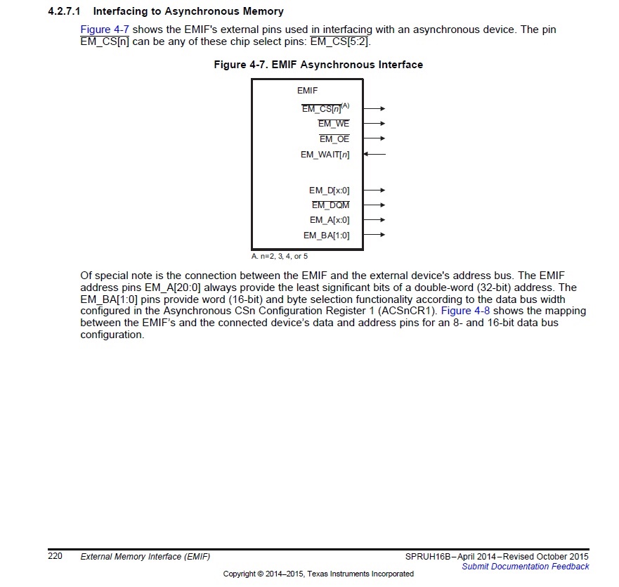
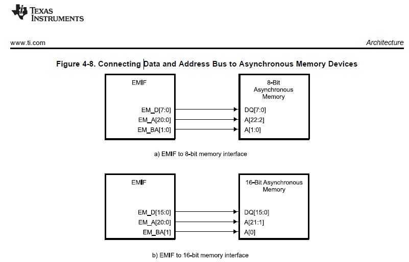
As regards the connection of addresses, the "spruh16b" datasheet on page 221 recommends the connection of Fig.4-8, type "B)",

therefore with A[0] of the Flash on EM_BA[1] of the DSP.


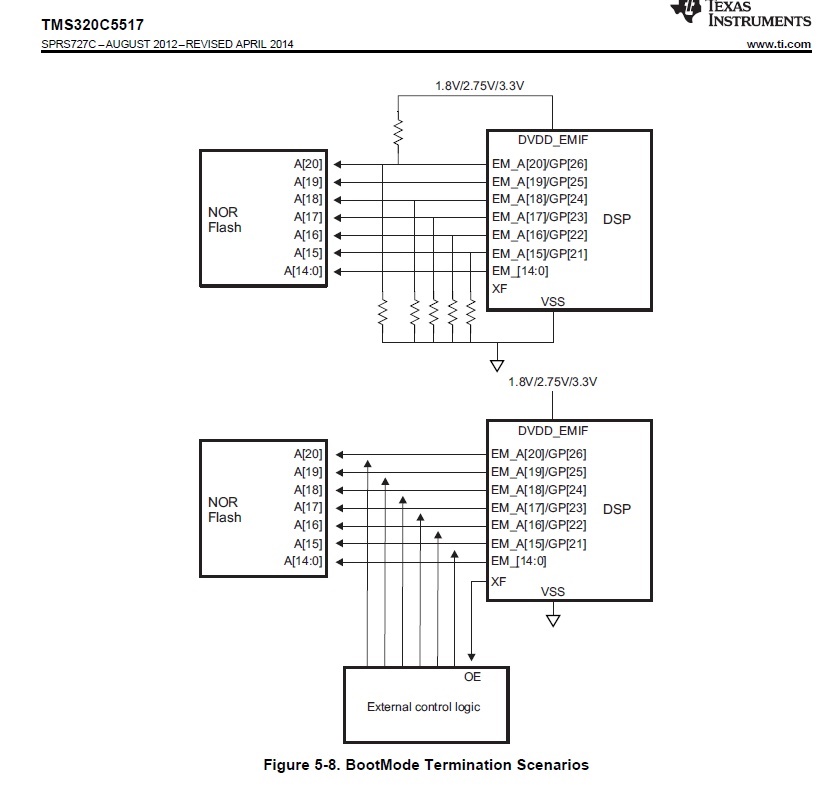
In the "SPRS727C" datasheet Page 76, for booting from NOR flash, the addresses A[14:0] are connected to EM_[14:0] of the DSP, therefore without using EM_BA[1].

How should I connect the addresses of my NOR Flash to the DSP, so that it boots correctly and can then use it as working memory?

Regards,

Daniele

  • Hi Daniele,

    The way the BA is used or not depends on the memory device you connected to the EMIF. Since the C5517 is a16-bit device, so it does not support byte addressable directly. If the memory device is byte addressable and has no BA interface, then you will need to use the BA1 as the A0. If the memory device is 16-bit addressable or it has a BA interface, then you do not need to use the BA in address lines.

    You can refer to the C5517 EVM design (C5517 EVM schematics) for details. The NOR flash (S29Gl128S11DHIV20) used via EMIF does not have BA interface. It has to use the BA1 for A0.

    The SDRAM (MT48H32M16LF), on the other hand has a BA interface, so you do not need to connect the BA1 to A0.

    Keep in mind, the NOR flash the C5517 ROM bootloader only support limited NOR flash devices. See 2.2.1 of sprabp1a.pdf for details.

    Best regards,

    Ming

  • Hi Ming,

    Sorry but what you tell me doesn't match what is reported in the datasheet, or I didn't understand.

    It is true that the 5517 has a 16-bit EMIF bus, but in the asynchronous interface,

    EM_A[20:0] addresses always provide double-word (32-bit) addressing.


    Therefore, as reported in chapter 4.2.7.1 of the SPRUH16B (shown above), a 16-bit asynchronous memory (NOR flash, SRAM, ETC.),

    must always have the address 0 (A[0]) connected to EM_BA[1] , while an 8-bit memory will always have A[0] connected to EM_BA[0] and

    A[1] connected to EM_BA[1], as per Fig.4-8 above.

    My flash is similar to the S29Gl128S11DHIV20 and in fact it was connected the same way.

    The question are:

    1) Why in the "SPRS727C" datasheet, to boot from 16-bit NOR Flash, the A[14:0] addresses appear to be connected to EM_[14:0]

         of the DSP, without using EM_BA[1], (diagram shown above) ?

    2) By connecting my Flash, as in the case of the S29Gl128S11DHIV20, will the boot be performed correctly?

    Regards,

    Daniele.

  • Hi, Ming

    To be precise, in our application we will use Flash Spansion S29AL016J.

  • Hi Daniele,

    Sorry for the incorrect information and confusion in the previous post.

    To answer you first question: The Figure 5-8 in "SPRS727C" datasheet, it is more to explain how the A[20:15] are used for boot mode pins. The description about A[14:0] is not accurate. You should use the Figure 4-8. Connecting Data and Address Bus to Asynchronous Memory Devices in TRM for connecting to the external NOR flash.

    The answer to your 2nd question: S29AL016J and S29Gl128S11DHIV20 are very similar, except the BYTE# should be set for 16-bit mode, while S29Gl128S11DHIV20 is 16-bit only.

    Best regards,

    Ming