This thread has been locked.

If you have a related question, please click the "Ask a related question" button in the top right corner. The newly created question will be automatically linked to this question.

TDA4VM: Some question about pinmux in A72

Part Number: TDA4VM
Other Parts Discussed in Thread: TDA4VH, SYSCONFIG

1、How to bind uart4 to /dev/ttyS6?

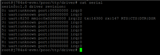
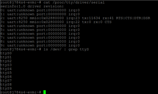
I have add below code in k3-j721e-common-proc-board.dts to test uart4 in A72. I thought uart4 should use '/dev/ttyS6', but as I test '/dev/ttyS0' bind to uart4.

	main_uart4_pins_default: main-uart4-pins-default {
		pinctrl-single,pins = <
			J721E_IOPAD(0x190, PIN_INPUT, 1) /* (W23) RGMII6_TD3.UART4_RXD */
			J721E_IOPAD(0x194, PIN_OUTPUT, 1) /* (W28) RGMII6_TD2.UART4_TXD */
		>;
	};

	&main_uart4 {
		status = "okay";
		pinctrl-names = "default";
		pinctrl-0 = <&main_uart4_pins_default>;
		/* Shared with ATF on this platform */
		power-domains = <&k3_pds 281 TI_SCI_PD_SHARED>;
	};

2、How to add the GPIO' pinmux in A72? I can not find a place to add it in k3-j721e-common-proc-board.dts.
I used below commands to read the GPIO0_28's level(GPIO0_28 connect to an input clock), but no any 0&1 change.

echo 280 > /sys/class/gpio/export
echo in > /sys/class/gpio/gpio280/direction
cat /sys/class/gpio/gpio280/value

After adding GPIO0_28's pinmux in rtos\ethfw\utils\board\src\j721e\board_pinmux_data.c, I read the GPIO0_28's level change 0&1 in A72. I find pinmux just write register, so anywhere is ok. But it's not in A72. This step is to ensure the input clock is ok, and the test method is right.

My SDK is My SDK version is ti-processor-sdk-rtos-j721e-evm-09_00_00_02&ti-processor-sdk-linux-adas-j721e-evm-09_00_01_02

  • Hi Zheng,

    As a disclaimer, this is my first time configuring UART as well, so your help would be greatly appreciated.

    As an experiment, I tried pinmuxing UART0 on a similar processor that I have set up in my office currently, TDA4VH. After pinmuxing and setting status = "okay", I added an alias for serial3 = &main_uart0 like the following in k3-j784s4-evm.dts (the equivalent for TDA4VM looks to be in k3-j721e.dtsi):

    aliases {
    serial2 = &main_uart8;
    serial3 = &main_uart0;
    mmc0 = &main_sdhci0;
    mmc1 = &main_sdhci1;
    i2c0 = &main_i2c0;
    };

    With these changes, I get the below results.

    Before UART0 initialization and alias addition:

    And after UART0 initialization and alias addition:

    And logs that also indicate ttyS3 is UART0 (aka, main_uart0: serial@0x280000 = ttyS3).

    As for GPIO, each GPIO should be controlled either by A72 through the device tree and Linux SDK, or the R5 cores through the board_pinmux_data.c file using RTOS SDK, but not both at the same time.

    For example, the following FAQ would be a guide for how to allow Linux to control GPIO pins: https://e2e.ti.com/support/processors-group/processors/f/processors-forum/918654/faq-tda4vm-dra829-am65xx-linux-configuring-gpios

    Regards,

    Takuma

  • As an experiment, I tried pinmuxing UART0 on a similar processor that I have set up in my office currently, TDA4VH. After pinmuxing and setting status = "okay", I added an alias for serial3 = &main_uart0 like the following in k3-j784s4-evm.dts (the equivalent for TDA4VM looks to be in k3-j721e.dtsi):

    I find ‘aliases serial6 = &main_uart4;’ already exist in k3-j721e.dtsi, and it does not work. I also add it in k3-j721e-common-proc-board.dts, no any help. As below shows, uart4 is link to ttyS0.

    root@j721e-evm:/proc/tty/driver# cat serial
    serinfo:1.0 driver revision:
    0: uart:8250 mmio:0x02840000 irq:195 tx:0 rx:0 DSR
    1: uart:8250 mmio:0x40A00000 irq:192 tx:0 rx:0 CTS|DSR
    2: uart:8250 mmio:0x02800000 irq:193 tx:13478 rx:69 RTS|CTS|DTR
    3: uart:8250 mmio:0x02810000 irq:194 tx:0 rx:0 DSR
    
    main_uart4: serial@2840000 {
    	compatible = "ti,j721e-uart", "ti,am654-uart";
    	reg = <0x00 0x02840000 0x00 0x100>;
    	interrupts = <GIC_SPI 196 IRQ_TYPE_LEVEL_HIGH>;
    	clock-frequency = <48000000>;
    	current-speed = <115200>;
    	power-domains = <&k3_pds 281 TI_SCI_PD_EXCLUSIVE>;
    	clocks = <&k3_clks 281 0>;
    	clock-names = "fclk";
    	status = "disabled";
    };
    

    For example, the following FAQ would be a guide for how to allow Linux to control GPIO pins: https://e2e.ti.com/support/processors-group/processors/f/processors-forum/918654/faq-tda4vm-dra829-am65xx-linux-configuring-gpios

    It does not help me, I already know how to use the GPIO.My question is withouting bind gpio to a device(can i2c...), how to control it in '/sys/class/gpio'. In other words, how to add add the GPIO' pinmux in A72.  In my test, add pinmux in rtos\ethfw\utils\board\src\j721e\board_pinmux_data.c is just a test to ensure the hardware is ok.

  • Hi Zheng,

    If gpiod/chardev and sysfs is not working, I will need a business day or two to take a look at the GPIO issues.

    However, for the UART issue I think I have located the issue. It seems like with 9.x SDK we removed a kernel config that specifies max UART instances, and a default value of 4 is pulled from somewhere.

    Adding this back to defconfig, rebuilding the kernel, and reflashing makes more serial instances appear in terminal:

    https://e2e.ti.com/cfs-file/__key/communityserver-discussions-components-files/791/0001_2D00_Re_2D00_add_2D00_max_2D00_UART_2D00_instances_2D00_to_2D00_10._2D00_Increasing_2D00_from_2D00_def.patch

    Since only 4 instances of serial is available without these configuration, it looks like the UART instances were assigned to any available serial instance, which causes main_uart4 to enumerate as ttyS0. In 8.6 SDK, we had set this to 10 instance, so this is an issue only seen with 9.0 - which I have reported to our SDK team about.

    Regards,

    Takuma

  • 0001-Re-add-max-UART-instances-to-10.-Increasing-from-def.patch

    After adding the patch, and replace the rootfs/boot/Image, uart4 map to ttyS6. 

    Please keep focus on the GPIO issue. Thank you so much.

  • Hi Zheng,

    For the GPIO, my first recommendation is to not define it in board_pinmux_data.c, and instead, define it in the device tree.

    Have you tried this out on your end?

    For example, here is what I get using the commandline gpiod for setting and getting GPIO0_28 before pinmuxing:

    root@j721e-evm:~# gpioset 4 28=1
    root@j721e-evm:~# gpioget 4 28
    0
    root@j721e-evm:~#

    And after pinmuxing in device tree, I get:

    root@j721e-evm:~# gpioget 4 28
    1
    root@j721e-evm:~# gpioset 4 28=0
    root@j721e-evm:~# gpioget 4 28
    0
    root@j721e-evm:~#

    For reference, here is the device tree changes I did on top of 9.0 SDK and using sysconfig for pinmuxing (https://dev.ti.com/sysconfig):

    https://e2e.ti.com/cfs-file/__key/communityserver-discussions-components-files/791/0001_2D00_Pinmuxing_2D00_GPIO0_5F00_28_2D00_as_2D00_input_2D00_pin.patch

    Regards,

    Takuma