Other Parts Discussed in Thread: TIDEP-0077, PCM1864, TIDEP-0099, TIDEP-0088
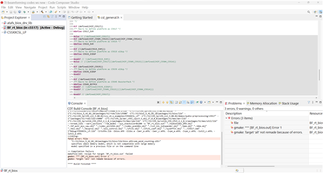
This is regarding the evaluation of the C5517 processor and its associated libraries, BF, ASNR, MSS and DRC features for developing the framework for our audio detection algorithm.
We wanted to proceed for POC with Circular Microphone Board + C5517 as per SPRACN7. Then we'll proceed for the development of final HW with similar interfaces.
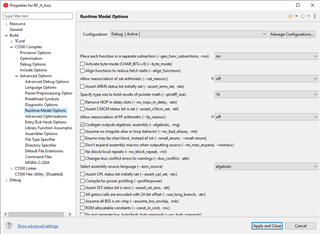
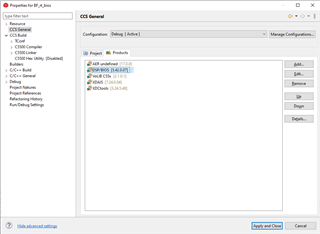
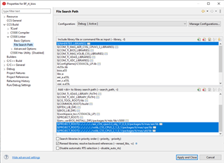
So for the SW integration and testing, it is mentioned that the following SW files are required.

I would like to understand how to get these and how to configure.
We need some guidance on using these tools and tuning the algorithms for our requirement.