This thread has been locked.

If you have a related question, please click the "Ask a related question" button in the top right corner. The newly created question will be automatically linked to this question.

TDA4VM: TDA4VM Jacinto 7 Boot up fail.

Part Number: TDA4VM
Other Parts Discussed in Thread: TPS6594-Q1,

Question: In what condition may cause the "nRSTOUT" triggered & closed the PMIC buck output?

Condition:

1.This IC power are from "TPS6594" PMIC output.

2.Some board can boot up successfully,but some couldn't. All of them with same PCBA、same layout、same materials.

Issue description:

1.PMIC buck & LDO do not output power so Jacinto 7 can't boot up.

2.Found that PMIC try to output power ,but PMIC pin25 "nRSTOUT" triggered,so the power got off.
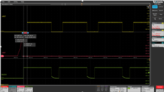
  • The "nRSTOUT" signal can be triggered and cause the PMIC BUCK and LDO outputs to reset under certain conditions. Here are the relevant details:

    1. ACTIVE_TO_WARM Sequence: The "nRSTOUT" and "nRSTOUT_SOC" signals are driven low during the ACTIVE_TO_WARM sequence, which can be triggered by either a watchdog or ESM_MCU error. In the event of a trigger, all BUCKs and LDOs are reset to their default voltages, but the PMICs remain in the ACTIVE state. (Doc: TPS65941212-Q1 and TPS65941111-Q1 PMIC User Guide for J721E, PDN-0B - Page 34)
    2. Watchdog Timer: The watchdog timer can be disabled if needed during initial development or if it's not required in the system. If it's desired to disable the watchdog through hardware, GPIO_8 is required and must be set high by the time "nRSTOUT" goes high. After "nRSTOUT" is high, the watchdog state is latched and the pin can be configured for other functions through software. (Doc: Optimized TPS65941213-Q1 and TPS65941111-Q1 PMIC User Guide for J721E, PDN-0C - Page 11)
    3. Error Signal Monitor: The PMICs are configured to monitor MCU and SoC error signals. For example, GPIO_7 of the primary TPS6594-Q1 PMIC is configured as the MCU error signal monitor and must be enabled through the ESM_MCU_EN register bit. Similarly, GPIO_3 of the primary TPS6594-Q1 PMIC is configured as the SoC error signal monitor, enabled through the ESM_SOC_EN register bit. (Doc: TPS65941212-Q1 and TPS65941111-Q1 PMIC User Guide for J721E, PDN-0B - Page 12,13)

    In your case, it's possible that the "nRSTOUT" signal is being triggered due to a watchdog or ESM_MCU error, causing the PMIC BUCK and LDO outputs to reset. This could be due to a variety of factors, such as a fault in the MCU or SoC, or a misconfiguration of the watchdog timer or error signal monitors.

  • Hi Derek,

    When you mention some boards cannot boot successfully, are there any failure logs from the terminal or its completely silent?

    Best Regards,

    Keerthy 

  • I believe you wanted to ask Johnny. Not me. I was trying to provide some answers. 

  • Derek,

    Okay. Thanks. 

    Johnny,

    When you mention some boards cannot boot successfully, are there any failure logs from the terminal or its completely silent?

    Best Regards,

    Keerthy 

  • I will check the watchdog & ESM error parts.

    -------------------------------------------------------------

    Besides,I still confused about the questions as below:

    1. In this case,why some of the PCBA could boot up but some couldn't?
    2. "TDA4VM" pin "H19、H21、J20" (VDDSHV1_MCU) power is from "TPS6594 VOUT_LDO2",this is a 1.8V power.

         -> If I disconnect this 1.8V and "VDDSHV1_MCU" connect to a 3.3V power,those boot up fail PCBA could boot up normally.
    So I don't know what's the different between 1.8v & 3.3V for this pin.

  • Hi Keerthy,

    For the TDA4VM side, the terminal do not have any response.

    But,I had read the register status on "TPS6594" to compare pass & fail.

  • Hi,

    I had read the register status on "TPS6594" to compare pass & fail.

    Which OS is being used? Do you have any boot logs on the failing boards?

    - Keerthy

  • No,the terminal which I used is Tera-term ,it do not have any response.

  • Hi Johnny,

    I will let our hardware expert comment on the failing boards as it seems to be a board level differences to me at this moment.

    - Keerthy

  • Hi,

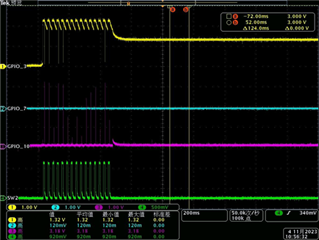
    I have measured the waveform between PMIC "TPS6594" on GPIO_3、GPIO_7、GPIO_10 & Buck output SW_B2.
    We could see that GPIO_7 is always low.
    Other signal looks try to pull high, but some error happened so pull low.

  • The PMIC has built-in safety mechanism that 'protect' the design from damage.  During power-up, if it detect and over-current condition or in-valid voltage condition - it will shutdown.  I think it retries several times - and then stops.  Is that what you are seeing on the failing boards?  Residual voltage is one of the PMIC checks - meaning if a voltage on one domain 'leaks' into another domain...it might trigger an alert in the PMIC.  When you change VDDSHV1_MCU from 1.8 to 3.3V, maybe that is the rail that was seeing the  invalid voltage.

  • Hi Robert,

    You think that maybe 1.8v from PMIC output have leak to other domain that triggered the alert?

    Or,maybe other volatge leak to the 1.8v place,is my understanding correct?

    So in this case, maybe the PCBA production may cause this problem to make some PCBA fail but some are good.

    ---------------------------------------------------------

    One more question,

    If the PMIC buck output net's layout diameter is not enough the withstand current, does this condition will trigger the PMIC alert?

    EX: PMIC Buck 4 mentions need 4A on the datasheet, but layout only set about 2A on this wired.

  • It is possible power from one domain is 'leaking' into another domain. Using a scope you can capture the power-up sequence on each rail.  If there is leakage, you should see it - as voltage will begin to exist on the power rail before the rail is enabled.  Its possible different boards have different leakage amounts (based on process variations of ICs) - so maybe some boards are exceeding the PMICs thresholds while others are not.  This is just a guess - you need to test/confirm.

    Could a small trace cause PMIC alert?  I don't think this will cause the PMIC alert, as it only checks that its regulated voltage is within its programmed margin.  The voltage may drop across the PCB (due to small trace) may cause the IC to fail if voltage drop is significant.  PMIC does check for over-current conditions.