

Hi,
I would like to ask a question on synchronization between VPBE and VPFE.
What if the input frame rate of VPFE input and output frame of VPBE are different? For example, it is very common that an image sensor has frame of 30 frame/sec, but for VPBE interfacing with LCD the typical frame rate could be 60 frame/sec. Therefore, within every 1/30 second there is one frame in, but two frames needs to be output to LCD.
If VPBE.OSD has a video window, say video 0, whose source is VPFE input, then how is video 0 updated? Should it be updated every 1/30 second according to input frame rate, or every 1/60 second according to output rate?
Further, what if the ratio between output and input frame rate are not whole integers? It is also common for image sensor to have 25fps input rate while LCD has 60fps rate, between which the ratio is 60:25=2.4, how does the synchronization work in this case?
There are two pieces of information I notice that might have relation to this synchronization problem:
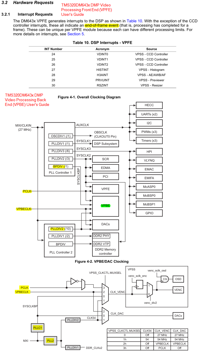
1. For VPFE, there are interrupts indicating end-of-frame events.
2. For VPBE, there are as many as four clock sources for VPBE.VENC, including PCLK which is VPFE's input clock.
So should VPFE.PCLK be used here? If it is used, although at the first glance there seems to be an apparently simple synchronization mechanism PCLK affords, if we think in more detail the case might not be as simple as expected. Because:
1. VPFE.PCLK is pixel level sync clock, not frame level clock. Frame sync signal VSYNC is either separately provided or embedded in video signal if the input stream if ITU/BT.656.
2. Interrupt events VDINT0 and VDINT1, perhaps also some others, are already capable effectively communicating the end-of-frame information.
Therefore, I am very curious in knowing the purpose of allowing PCLK to be VPBE.VENC's clock input. What is the purpose of this design? And how could it address the frame synchronization between arose due to different input/output frame for video stream?
Besides VPFE.PCLK, does other three clock sources (PLLC1, PLL2, VPBECLK) of VPBE help? In detail, how?
Thanks,
Zheng

