Hi, TI expert!
I would like to ask how to configure the MOSI pin of SPI as a push-pull output.
Regards,
Li
This thread has been locked.
If you have a related question, please click the "Ask a related question" button in the top right corner. The newly created question will be automatically linked to this question.
Hello li weiyu
Thank you for the query.
I would like to ask how to configure the MOSI pin of SPI as a push-pull output.
Help me understand what you mean by push pull. Most of the SoC IOs are LVCMOS.

Since you did not specify the SPI instance, i picked the SPI0.
There is a pad config register that you could use to configure the required functionality for the IO.
Regards,
Sreenivasa
Hello Sreenivasa,
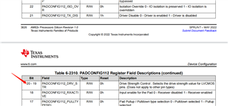
The push-pull output I mentioned actually refers to the bit[20:19] of the PADCONFIG112 register, as shown in the diagram below. I would like to ask, can the PADCONFIG112_DRV_STR field be configured directly in the device tree? If not, how should it be configured and are there any configuration reference methods available?
Regards,
Li
Hello li weiyu
Please use the latest TRM and let me know if you have any question.
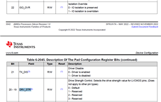
We do not support configuring the drive strength.
Regards,
Sreenivasa
Hello Sreenivasa,
I have a development environment for am6234, with our own evaluation board.
The software SDK version is PROCESSOR-SDK-LINUX-RT-AM62X-08.06.00.42.
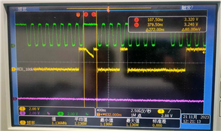
When we are using SPI0 , there is a problem with the high level waveform of MOSI (the SPI_D0 pin), as shown in the figure below:
The configuration of the device tree is as follows:


We suspect that this is caused by insufficient drive strength of the SPI_D0 pin. If the drive strength of the pin cannot be configured, how can this problem be solved?
Regards,
Li
Hello Li,
Thank you.
Please elaborate the issue you are seeing. Is the dipping of the waveform your concern?
Would you be able to share the schematics for a quick check.
Are you connecting SPI to multiple devices?
You might want to so a quick simulation to see if this is being observed.
Regards,
Sreenivasa
Hello Sreenivasa,
"Is the dipping of the waveform your concern?"
Yes, the waveform circled in red in the figure below does not meet expectations

“Would you be able to share the schematics for a quick check.”
Sorry, we have confidentiality requirements and the schematic diagram cannot be shared at the moment.
Is this issue closely related to hardware?
“Are you connecting SPI to multiple devices?”
Yes, we have currently connected two SPI devices to the AM6234.
Regards,
Li
Hello Li,
Thank you.
The DIP may not be due to the drive strength. - When does the DIP happen. Is it on a specific board or happens on multiple boards.
When the DIP happens are the power supply to the attached devices stable.
Is the IO levels same for the SoC and the attached device.
Is this issue closely related to hardware?
Hardware and the connections including the powering of the attached devices.
The SoC IOs and the attached devices have to be powered together.
“Are you connecting SPI to multiple devices?”
Yes, we have currently connected two SPI devices to the AM6234.
You could face signal integrity issues. I would suggest disabling one of the device and doing some tests.
Do you have pullup on the MOSI pin near to the attached device?
Regards,
Sreenivasa
Hello Tony,
Thank you.
Can you please elaborate your inputs.
Hello Li, could you please help answer some of the queries i added in the above thread.
Regards,
Sreenivasa
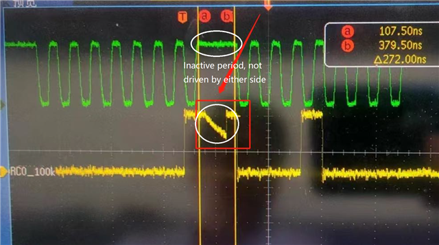
It is inactive period between two byte access, the CS must also be inactive although it is not captured in the picture, the data line is not driven, it is hi-z, so drift, nothing relevant to driver strength. no need care about it.
driver strength should impact rising edge.
Hello Tony,
Thank you for the inputs and appreciated.
It is inactive period between two byte access, the CS must also be inactive although it is not captured in the picture, the data line is not driven, it is hi-z, so drift, nothing relevant to driver strength. no need care about it.
driver strength should impact rising edge.
Hello Li, could you please help answer some of the queries i added in the above thread and also confirm if the inputs provided by tony is in line with the observations.
Out suggestion has been to add a pullup near to the attached devices since the SoC buffers are disabled when the interface is inactive.
Please refer to the above queries i have for you.
Regards,
Sreenivasa
Hello Li,
I found this thread that you could reference.
Although this is for a different processor, the explanation should be relevant.
(+) AM3352: SPI MOSI signal is abnormal - Processors forum - Processors - TI E2E support forums
M3352 SPI setting is as below:
AM33XX_IOPAD(0x8f0, PIN_OUTPUT_PULLDOWN | MUX_MODE7) /* F17, FLASH_WP */
AM33XX_IOPAD(0x950, PIN_INPUT_PULLUP | MUX_MODE0) /* A17, SPI_CLK */
AM33XX_IOPAD(0x954, PIN_INPUT_PULLUP | MUX_MODE0) /* B17, SPI_MISO */
AM33XX_IOPAD(0x958, PIN_OUTPUT_PULLUP | MUX_MODE0) /* B16, SPI_MOSI */
AM33XX_IOPAD(0x95c, PIN_OUTPUT_PULLUP | MUX_MODE0) /* A16, SPI_CS */
but SPI MOSI signal is abnormal

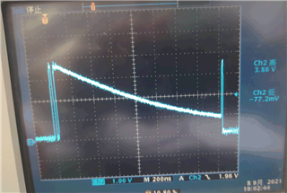
Could you give me some suggestions?
This looks ok. The SPI Data output signal goes hi-z when not driving. If you probed the clock together with the data then you will see that the data is driven during transfers. You can add a pulldown resistor if required.
Regards,
Sreenivasa