This thread has been locked.

If you have a related question, please click the "Ask a related question" button in the top right corner. The newly created question will be automatically linked to this question.

AM3352: DDR output driver impedance setting

Part Number: AM3352

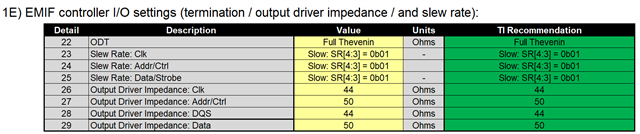
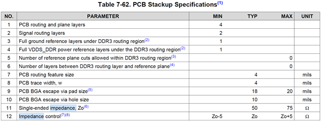
#1. In the EMIF tools, TI recommend output driver impedance CLK, DQS is 44ohm, but on datasheet, single ending impedance range is 50- to 75ohm, +-5ohm, should it at least 45ohm?

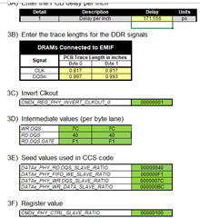
#2. About the PCB delay, customer wants to compatible with 2 PCB vendor, the two vendor's PCB Dielectric parameters are different. one is 181.604ps/inc, one is 171.556 ps/inc. which result in difference in Seed values. 

Can the two PCB use one parameter?


  • #1, The value in the spreadsheet is the output driver impedance of the IO buffer, and the spec you point to is the trace impedance of the board.  The recommendation is simply a good value to start with, you may have to adjust based on your board design to achieve impedance matched signals.  Also note that DQS and clk are differential signals

    #2 Those 2 delays are virtually the same relative to the frequency of operation.  I think you should be able to use a common set of parameters for both PCBs

    Regards,

    James


  • I think you should be able to use a common set of parameters for both PCBs

    Thanks, That is customer wanted. How to determine a common set? use average value of two PCB?

    Is it worth to use SW leveling to get optimized value of two PCBs, and use the average value of two PCBs?

  • Tony, yes you should be able to use the average of the two PCBs. 

    If they are just using one DDR3 without VTT, then i think you could just use the values from the spreadsheet.  You would not need to run SW leveling.  Since we are not pushing high operating frequencies on AM335x (max is 400MHz), there should be plenty of margin with a common set of values.  

    Regards,

    James