This thread has been locked.

If you have a related question, please click the "Ask a related question" button in the top right corner. The newly created question will be automatically linked to this question.

TMS320C6655: EMIF DATA RATE ISSUE

Part Number: TMS320C6655

Hi,

       We are using TMS320C6655 DSP processor. We have tried with EMIF interface with DMA transfer as well as without DMA.

We are getting the data rate with maximum of 5 MHZ approximately whereas ,it should be 32 MHZ max according to the theoretical data.

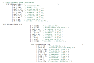
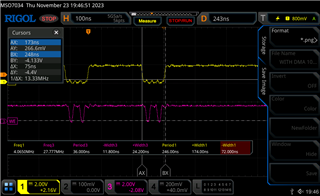
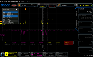
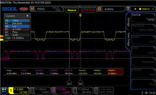
 I will share the probing images with frequency and width time period datas.

 Please look into it and kindly support for the low data rate query.

 Probing datas are with Chip select and write enable pin


Regards,

 Thilak

  • Thilak,

    Whenever the data rate is slow, check the module clock of EMIF. 

     IMPORTANT -------> SYSCLK3: 1/2-rate clock used to clock the MSMC, HyperLink, and DDR EMIF ( Page no: 85 - https://www.ti.com/lit/ds/symlink/tms320c6655.pdf )

    What is the core frequency of TMS320C6655 - DSP ?

    Accordingly the EMIF clock will also vary which will affect the data rate.

    Regards

    Shankari G

  • Hi Shankari,

               I have sent a query for EMIF16 peripheral ,not DDR EMIF that you have mentioned.EMIF16 interface is being used where we face low data rate issue.

    Please suggest.

  • Tilak,

    C6657 has both 32-bit-DDR-EMIF and EMIF16.

    For EMIF16:-

    SYSCLK7: 1/6-rate clock for slow peripherals (GPIO, UART, Timer, I 2C, SPI, EMIF16, McBSP, and so forth.) and sources the SYSCLKOUT output pin.

    The EMIF16 module provides an interface between DSP and external memories such as ASRAM, NAND and NOR flash - "Asynchronous".

    What memory flash you use? 

    According to the datasheet of your "flash-memory" - NAND ( or) NOR , the timing parameters has to be calculated.

    Please refer here:- https://www.ti.com/lit/ug/sprugz3a/sprugz3a.pdf

    2.5.2 Programmable EMIF16 Parameters

    The setup, strobe and hold parameters are in terms of EMIF16 clock cycles. Note that EMIF16 is clocked at CPU/6 (166.67 MHz for 1 GHz CPU frequency). The setup, strobe and hold values for reads can be calculated as follows (assume CPU=1 GHz). Determine the read cycle time from device datasheet (tRC). Now tRC = r_setup + r_strobe + r_hold. For example, if tRC = 86ns, 86 = r_setup + r_strobe + r_hold. Since each of the 3 parameters are in terms of CPU/6, (86/6) = r_setup + r_strobe + r_hold. This should be rounded off to the next higher integer, in this case 15. Determine from the memory device datasheet timing diagrams what each of the 3 parameters should be. After rounding off, always add the extra memory cycle(s) to the strobe. Similarly, w_setup, w_strobe and w_hold can be determined.

    ----

    For reference use the NAND flash memory used in the C6657 EVM.

    Steps:

    1. Refer the NAND part number used in the schematics of C6657 EVM

    2. Get the datasheet of the NAND flash part number

    3. Compare the timing parameters set for the NAND flash in the sample example of platform test - source code of PROCESSOR-SDK-RTOS-C665x 06_03_00_106 http://software-dl.ti.com/processor-sdk-rtos/esd/C665x/latest/index_FDS.html

    typedef struct {
    volatile Uint32 RCSR;
    volatile Uint32 AWCCR;
    volatile Uint8 RSVD0[8];
    volatile Uint32 A0CR;
    volatile Uint32 A1CR;
    volatile Uint32 A2CR;
    volatile Uint32 A3CR;
    volatile Uint8 RSVD1[32];
    volatile Uint32 IRR;
    volatile Uint32 IMR;
    volatile Uint32 IMSR;
    volatile Uint32 IMCR;
    volatile Uint32 IOCR;
    volatile Uint32 IOSR;
    volatile Uint8 RSVD2[8];
    volatile Uint32 NANDFCTL;
    volatile Uint32 NANDFSR;
    volatile Uint32 PMCR;
    volatile Uint8 RSVD3[4];
    volatile Uint32 NFECCCE0;
    volatile Uint32 NFECCCE1;
    volatile Uint32 NFECCCE2;
    volatile Uint32 NFECCCE3;
    volatile Uint8 RSVD4[4];
    volatile Uint32 IODFTEXECNT;
    volatile Uint32 IODFTGBLCTRL;
    volatile Uint8 RSVD5[4];
    volatile Uint32 IODFTTLAMISR;
    volatile Uint32 IODFTTLDMISR;
    volatile Uint32 IODFTTLDCMISR;
    volatile Uint8 RSVD6[20];
    volatile Uint32 MODRELNUM;
    volatile Uint8 RSVD7[8];
    volatile Uint32 NANDF4BECCLR;
    volatile Uint32 NANDF4BECC1R;
    volatile Uint32 NANDF4BECC2R;
    volatile Uint32 NANDF4BECC3R;
    volatile Uint32 NANDF4BECC4R;
    volatile Uint32 NANDFEA1R;
    volatile Uint32 NANDFEA2R;
    volatile Uint32 NANDFEV1R;
    volatile Uint32 NANDFEV2R;
    } CSL_Emif16Regs;

    Regards

    Shankari G

  • Hi,

     I have shared the emif configuration settings that we are using .We have configured with minimum as well as maximum values for the setup,strobe and hold But there isn't much difference


  • Thilak,

    What memory flash you use? 

    If NAND, please share the part number of NAND memory and its datasheet.

    Regards

    Shankari G

  • Hi Shankari,

                   EMIF16 peripheral We are using for communicating between dsp and Cyclone5 Fpga. We are sending data from DSP to FPGA and probing the DSP EMIF (WE and CS) signals.

    Thats the data that has been shared.

    Pls revert.

    Regards,

    Thilak

  • Thilak,

    Please give details about how the Cyclone5 FPGA is configured-and-interfaced to the EMIF16 of C6657.

    Regards

    Shankari G