This thread has been locked.

If you have a related question, please click the "Ask a related question" button in the top right corner. The newly created question will be automatically linked to this question.

TDA4VM: LD3 blinking red on Processor board PROC079A

Part Number: TDA4VM

Hello TI Team,

The processor board is completely offline. There are no logs displayed using minicom via serial port. This happened all of a sudden, the board stopped working.
Is there any fix to this?
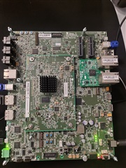
I am attaching an image of the board for your reference.

Thank you,

Best Regards,

Akhil

  • What voltage are you providing as input?  RED led typically means an invalid voltage is being supplied.  However - I don't think its normal for both GREEN (LD2) and RED (LD3) to be on at same time, as shown in your picture.  Can you measure the voltage on test point TP20?

  • Hi Robert,

    The power supply to the Ti Board is via the 220V AC to 12V DC and 5A  adapter. 

    Based on a similar forum thread,

    TDA4VM: Proc079A development board cannot be started. LD3 is flashing, but the external input power is 12V - Processors forum - Processors - TI E2E support forums,

    I have recorded voltages at several test points.

    TP19
    EVM power switch on - 8.17 V
    EVM power switch off - 11.28 V

    TP20
    EVM power switch on - 7.80 V
    EVM power switch off - 0.15 V

    TP35
    EVM power switch on - 3.25 V
    EVM power switch off - 0 V

    TP130
    EVM power switch on - 3.26 V
    EVM power switch off - 0 V

  • Voltage at TP19 feeds voltage at TP20.  When the board is off, the input voltage should be at TP19 (11.28V) and TP20 should be 0V (0.15V).  OK

    When the board is ON, the voltage at TP19 should still be same as input voltage, but its not (8.17V).  TP20 is similar voltage, slightly lower due to circuit (7.80).  Issue seems to be with either FUSE (F1) or the protection FET circuit (U4, U107).  Have you tried replacing the fuse?   The board comes with a spare mounted (F2).  Or you can measure the voltage on each side of the Fuse to make sure same (when switch is ON).

  • Hi Robert,
    I measured the voltage across the two ends of the fuse(F1) i am observing that on both sides of fuse with the GND, voltage is fluctuating between 7V-8V.
    I am observing similar voltages, but am unsure of how to remove and replace F1 with F2 fuse, can you guide me in this regard?

    Fuse F1

    on - both side of fuse voltage is fluctuating b/w 7-8v

    Fuse F2

    on - 0V on both sides

    Protection FET Circuit
    I am getting 7.7V at U4, what is the expected value there?

    I was difficult to find U107 on the board it would be helpful if you could send the board's schematic/layout diagram.

  • There is an issue if voltage is already dropped to 7-8V at fuse.  This implies the input supply is not providing correct voltage (12V) or not providing enough current (5A).  Do you have another supply you can try, or better yet do you have a lab bench supply that can supply voltage and provide current?

    Its possible the board is damage and pulling TOO MUCH current (more than supply can provide).  Or its possible the supply is not providing correct input power.