


Hello, I have a concern about what I am seeing in the Sitara Clock Tree Tool regarding the clock frequency to the OCMC_RAM1 module. I am trying to confirm the clock speed to OCMC_RAM1, which I want to be 266 MHz. Please see the screenshot below.
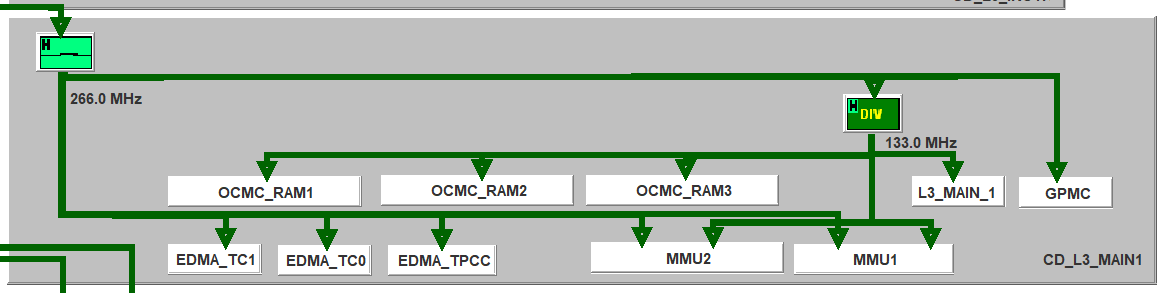
The clock coming in to Switch_L3MAIN1_L3_GICLK (top left hardware switch) is L3_ICLK; the output of the switch is L3MAIN1_L3_GICLK. The tool shows (using a register dump that was uploaded from my device) that the frequency of this clock is 266 MHz.
According to Table 5-9 of the AM5726 datasheet, the maximum supported frequency to OCMC_RAM1 (input clock name OCMC1_L3_CLK) is 266 MHz, which is what I want, and its source is L3MAIN1_L3_GICLK. So far so good... but the Clock Tree Tool (CTT) is showing a hardware divide by two ("DIV" in the screenshot) prior to the OCMC_RAM1 module. So the CTT is showing a clock frequency of 133 MHz going to OCMC_RAM1.
Also, when I go to Run > Frequency Analyzer in the CTT, it shows that the "Current Clock Running (MHz)" of instance OCMC_RAM1 is 133 MHz, but the "Max Clock Allowed" is 266 MHz.
I have not been able to find documentation of this supposed hardware divide by two. If it really does exist, then according to the screenshot, there is nothing that I can do to get a 266 MHz input clock to OCMC_RAM1 (because I am fairly certain that the input to the divider, L3MAIN1_L3_GICLK, cannot exceed 266 MHz itself). Can you please shed some light on what I am seeing? Is this a bug with the CTT, or is my OCMC_RAM1 really running at 133 MHz?
Thanks in advance, and best regards,
Dave

