This thread has been locked.

If you have a related question, please click the "Ask a related question" button in the top right corner. The newly created question will be automatically linked to this question.

AM62A7: am62a1, mcu use gpio to trig dma

Part Number: AM62A7

hi

when am62a mcu use  12 mcu_gpios(such as mcu_gpio0_0 to mcu_gpio0_11) connect to 12 ak1 radars, the mcu_gpios config as input, and ak1 radar send  data.

we want use udma work as:  when one mcu_gpio recv a Rising edge or Falling edge,the udma auto read the GTC timer count and write to the memory which we config; from zhcab72.pdf gpio+udma cap pwm

1. How many udma we can use in the scene ?

2.  a udma can be trigged by any mcu_gpios(such as mcu_gpio0_0 to mcu_gpio0_11) ?

  • Hi,

    What OS uses the MCU GPIO on AM62Ax, Linux or RTOS?

  • mcu use rtos

  • Hi,

    I am routing your query to our RTOS expert for comments.

  • Hello ,

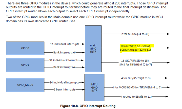
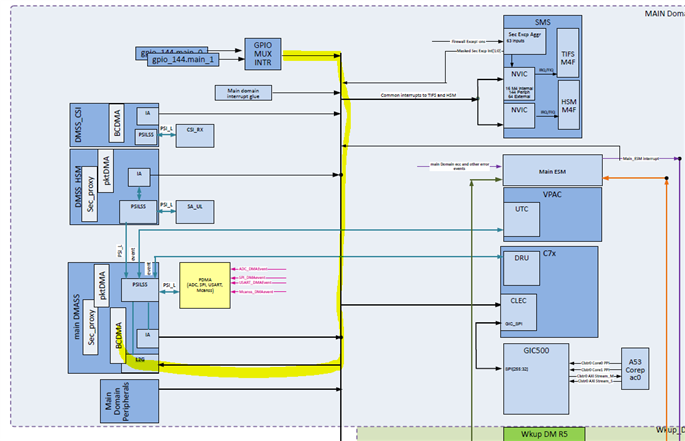
    Please look at the images below.

    There are main GPIOs and MCU GPIOs.

    If you see the yellow highlighted color, which triggers BCDMA through the main GPIO's and not with the MCU_GPIO's,.

    So, it is not possible to trigger BCMDA with MCU_GPIO's.


    Please look at the below link, and the same example (GPIO+BCDMA) is available on the below repository.

    https://github.com/TexasInstruments/Beyond-SDK

    we want use udma work as:  when one mcu_gpio recv a Rising edge or Falling edge,the udma auto read the GTC timer count and write to the memory which we config; from zhcab72.pdf gpio+udma cap pwm

    I understood that based on the above point, if any rising or falling edge occurs, you need to transfer GTC time and write the same count in some PWM registers.

    I am proving my reply based on the above point. Please correct me if my understanding is wrong.


    In the above case, before GPIO should trigger DMA transfer with the known data, DMA needs to get the GTC time value, and next, it should write in source memory so that DMA will transfer data from memory to memory. Here, UDMA does not have the capability to automatically read GTC data. This use case (Auto-Trigger BCDMA) will be used if source data is already available and wants to be sent for every rising edge.


    One more thing is that when this Risign edge or falling edge occurs when you want to transfer GTC data and it has 64-bit and mostly DMA, it is not recommended for this type of application for sending lower bytes. If you have large data sets, then it is really helpful if you use the DMA.


    Why you can't implement this method with simple GPIO IRQ Just enable bank interrupts for all mcu_gpio pins, then you may get an interrupt for any rising edge or falling edge, then read gtc time and put them in one memory, which is a simple use case and sending for smaller databytes; we don't need to use dma.


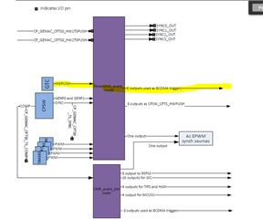
    Please look at the below image. By using CMP_EVENTS or GTC HW push, we can also auto-trigger BCMDA and see if this helps with your requirement.


    If you want to explore GTC +GPIO+ UDMA auto-triggers, just use the examples below. And try; in your use case, the source address would be the GTC Register address.

    https://github.com/TexasInstruments/Beyond-SDK

    Regards,

    S.Anil.

  • Hello,

    If you want to explore GTC +GPIO+ UDMA auto-triggers, just use the examples below. And try; in your use case, the source address would be the GTC Register address.

    I assume that the above case is also possible; just explore the auto-trigger examples available on AM64X and AM62X, and instead of giving source addresses of any memory location, give a GTC timer Register address , but again, we are using DMA for lower data bytes, which is not recommended.

    Regards,

    S.Anil.

  • thank you 

    we want use udma work as:  when one mcu_gpio recv a Rising edge or Falling edge,the udma auto read the GTC timer count and write to the memory which we config; from zhcab72.pdf gpio+udma cap pwm

         -->    I understood that based on the above point, if any rising or falling edge occurs, you need to transfer GTC time and write the same count in some PWM              registers.

     sorry,it is my fault, what i mean is:   the ak1 will send pwm to mcu or main gpio,  we need to get the pwm width.

    if we use gpio irq, when gpio recv a Rising edge or Falling edge,then in  irq handler we read  GTC timer and save it to mem_0, and next save it to mem_1 after 10  or 20 times, we disable irq, then we start to analysis the  time in mem_0-mem_20, so we can get pwm width;

    but this gpio+irq will consume cpu, and irq may not be respond fast; so in  zhcab72.pdf (from ti) ,it recommend use gpio+udma to cap pwm width.
    and am62a connect 12 ak1.  Up to 2 ak1 working simultaneously, so it need 2 dma working simultaneously. one ak1 connect to one gpio, so the  different gpio will trig the 2 dma in different time.
  • Hello ,

    so in  zhcab72.pdf (from ti)

    Is it possible to share the above document? I am not familiar with this document.

    Now, I understand your radar sends a PWM signal, which you wanted to connect to the GPIO, and from this GPIO event, you wanted to trigger data.

    Which data did you want to transfer? Is it the GTC timer counter value?

    and am62a connect 12 ak1.  Up to 2 ak1 working simultaneously, so it need 2 dma working simultaneously. one ak1 connect to one gpio, so the  different gpio will trig the 2 dma in different time.

    So, total, you have 12 radars, of which 2 radars are connected to two GPIO's.

    One GPIO can be used to store GTC timer values in one memory location.

    Another GPIO can be used to transfer GTC timer-stored buffer values to a different memory location.

    Here, how many GTC samples are stored in 1st channel?

    When we need to send data of second channel ?

    Regards,

    S.Anil.

  •  zhcab72.pdf  from https://www.ti.com.cn/cn/lit/an/zhcab72/zhcab72.pdf?ts=1701852745251&ref_url=https%253A%252F%252Fcn.bing.com%252F

    we have 12 radars, every radar just connect one gpio to am62a, so all 12 gpios;

    12 radars not work simultaneously, Up to 2 radars working simultaneously, we first use 0-1 radars,after 30ms we use 2-3 radars... ;

    when one radars works, it first send a pulse on one gpio, then if radar detect an obstacle,then it send pulse again, if there are many obstacles, the radar may send many pulse; am62a get  every pulse arrival time,Based on time intervals we can calculate the distance to the obstacle.

    when 0- radar work, gpio-0 to trig dma-0 to save every pulse time from gtc timer to memory array ,1- radar work with  0- radar simultaneously, 1- radar use gpio-1 to trig dma-1 to save every pulse time from gtc timer to other memory array .

    when 2- radar work, gpio-2 to trig dma-0 to save every pulse time from gtc timer to memory array ,3- radar work with  2- radar simultaneously, 3- radar use gpio-3 to trig dma-1 to save every pulse time from gtc timer to other memory array .

    so it need two dma work simultaneously;  and multiple gpios may trig same dma in different time periods.

    so i ask:

    1. How many udma channel  we can use in the scene ?

    2. one udma channel can be trigged by  multiple gpios  in different time periods.?

  • Hello,

    I am looking at your answers , and you may expect a reply by today.

    Regards,

    S.Anil.

  • hello,

    Is there any progress on the issue? thank you

  • Hello,

    I am not able to find the above document in the English format, and I am checking with TI Teams to get it in the English format.

    If you have English format pdf , please share it with me. I got replies from other teammates about this document and will provide a reply by EOD.

    Regards,

    S.Anil.

  • sorry, i don't have English format.

    our  radar is similar to  E524.09,one io  communicate,can you refer to  E524.09 spec ?

  • Hello ,

    one udma channel can be trigged by  multiple gpios  in different time periods.?

    Now, I understand your application, and you are using the below method.

    One GPIO pin should store the GTC time for every rising edge or falling edge. So, for every rising or falling edge, GTC time should be stored in one memory location, and the next GPIO pin should be used to transfer the data from the GTC source buffer to the destination buffer.

    You need the below approach for achieving your application.


    12 main GPIO pins and 12 UDMA channels are needed.

    One GPIO and one UDMA channel can be used to store GTC time, and another GPIO and UDMA channel can be used to transfer stored GTC time.

    But currently, in the AM62A device, we have 10 main GPIO router outputs that can be used to auto-trigger DMA, which is not possible with 12 radars, and we should go with 10 radars. Here, I never tried DMA for transferring 64-bit data since in this use case, the first channel should store the GTC time for every rising edge or falling edge.

    If you want to explore GPIO+ UDMA auto-triggers examples , please use the below link. Examples are available on AM64X and AM62X, and the same approach should be applicable to AM62A devices as well.

    https://github.com/TexasInstruments/Beyond-SDK

    2. one udma channel can be trigged by  multiple gpios  in different time periods.?

    For auto DMA trigger use cases during initializations, we need to allocate one dedicated channel for each UDMA +GPIO operation.

    In your use case, two radars work simultaneously, and you can use two dedicated channels in this case every time you enable and disable channels for each radar set.


    EX:

    Use 0 and 1 UDMA channel trigger data, and after operation is done for the first set of radar, next disable the channels of the first set of radar, and assign the same channels to the next set of radar, and so on. In this way, you can do it, but initializing  UDMA during running is not good.

    You don't need to bother about UDMA channels there are many channels are available  on AM62A devices .


    Regards,

    S.Anil.

  • thank you

    -->But currently, in the AM62A device, we have 10 main GPIO router outputs that can be used to auto-trigger DMA
    if 12 gpios is gpio0_0-gpio0_11, if we need 10 radars work simultaneously,  we need 10 UDMA channels , the UDMA channels is enough ?

    -->One GPIO and one UDMA channel can be used to store GTC time, and another GPIO and UDMA channel can be used to transfer stored GTC time.

    all 12 GPIOs ' Rising edge or Falling edge GTC time need be save;


    gpio0_0-gpio0_11 can be dynamical ro route to 10 gpios which can trig dma ?, such as  :ues gpio0_0-gpio0_9  to trig 10 dma, then change gpio0_2-gpio0_11  to trig the10 dma ?

  • if we need 10 radars work simultaneously,  we need 10 UDMA channels , the UDMA channels is enough ?

    Yes, you can connect 10 radars, and you need 10 dedicated UDMA channels since AM62A has 10 GPIO Router output's channels to trigger auto-DMA.

    -->One GPIO and one UDMA channel can be used to store GTC time, and another GPIO and UDMA channel can be used to transfer stored GTC time.

    all 12 GPIOs ' Rising edge or Falling edge GTC time need be save;

    Yes, all channels can store the GTC time for every rising and falling edge. You have to configure the GPIO trigger type for both the rising edge and the falling edge.

    Actually, as mentioned above, the AM62A has only 10 GPIO router outputs. So, you can connect 10 radars and 10 dedicated UDMA channels.

    gpio0_0-gpio0_11 can be dynamical ro route to 10 gpios which can trig dma ?, such as  :ues gpio0_0-gpio0_9  to trig 10 dma, then change gpio0_2-gpio0_11  to trig the10 dma ?

    I am explaining the above answer for 10 radars and not for 12 radars since we have only 10 GPIO router outputs, which can accommodate only 10 radars.


    EX: GPIO0 - > GPIO 9 pins used and 10 dedicated UDMA channels allocated for auto-trigger dma based on edge signals.

    Now, you wanted to change triggers DMA from different GPIO's, like GPIO2 > GPIO11, with the same 10UDMA channels.

    Yes, it is possible. In the above use case, you have reinitialized the UDMA channel allocation for the corresponding GPIO pins.

    Regards,

    S.Anil.

  • Hi Swargam,

    Is it possible to use ecap to receive the signal and trigger UDMA interrupt? If this is possible, then we can use GPtimer and EPWM together to get 12 USS.

  • Hello Adam Hua,

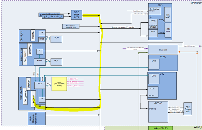
    I have looked at AM62A SOC TRM and this is not possible, and there are no UDAM triggers from the ECAP Module. Please look at the below images.

    So, UDMA triggers are not possible from ECAP modules.

    Regards,

    S.Anil.