Other Parts Discussed in Thread: SK-AM64B
Hi,
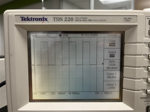
I'm trying to get 1-PPS out of SK-AM64B. I followed the recommendation from this thread, but I wasn't able to get 1-PPS out of J3 (on SK-AM64B board this is SYNC0_OUT_TP --> my understanding it's a typo in schematic to call it SYNC1_OUT_TP, SYNC0_OUT_TP is correct).
This is what I updated to... except I also tried PIN_OUTPUT, seemed like it should be an output. Neither allowed me to see 1-PPS on J3.
main_ecap0_pins_default: main-ecap0-pins-default {
	pinctrl-single,pins = <
		AM64X_IOPAD(0x0270, PIN_INPUT, 1) /* (D18) ECAP0_IN_APWM_OUT -> SYNC0_OUT */
	>;
};
Although I don't think I've got this.... is this in the #include <dt-bindings/net/ti-dp83867.h> --> Don't have my linux box up to check.
cpsw_cpts_pps: cpsw-cpts-pps {
pinctrl-single,pins = <
/* pps [cpts genf1] in22 -> out37 [cpts hw8_push] */
TS_OFFSET(37, 22)
/* pps [cpts genf1] in22 -> out26 [SYNC1_OUT pin] */
TS_OFFSET(26, 22)
>;
};
};
---
So I'm wanting to test the accuracy of aligning 1-PPS with PTP on some SK-AM64B boards, so need to get this working.
Thanks for your assistance. Attached is the DTS I'm working with.
73,
Timothy
// SPDX-License-Identifier: GPL-2.0
/*
* Copyright (C) 2021 Texas Instruments Incorporated - https://www.ti.com/
*/
/dts-v1/;
#include <dt-bindings/mux/ti-serdes.h>
#include <dt-bindings/phy/phy.h>
#include <dt-bindings/gpio/gpio.h>
#include <dt-bindings/net/ti-dp83867.h>
#include <dt-bindings/leds/common.h>
#include "k3-am642.dtsi"
/ {
compatible = "ti,am642-sk", "ti,am642";
model = "Texas Instruments AM642 SK";
chosen {
stdout-path = "serial2:115200n8";
bootargs = "console=ttyS2,115200n8 earlycon=ns16550a,mmio32,0x02800000";
};
memory@80000000 {
device_type = "memory";
/* 2G RAM */
reg = <0x00000000 0x80000000 0x00000000 0x80000000>;
};
reserved-memory {
#address-cells = <2>;
#size-cells = <2>;
ranges;
secure_ddr: optee@9e800000 {
reg = <0x00 0x9e800000 0x00 0x01800000>; /* for OP-TEE */
alignment = <0x1000>;
no-map;
};
main_r5fss0_core0_dma_memory_region: r5f-dma-memory@a0000000 {
compatible = "shared-dma-pool";
reg = <0x00 0xa0000000 0x00 0x100000>;
no-map;
};
main_r5fss0_core0_memory_region: r5f-memory@a0100000 {
compatible = "shared-dma-pool";
reg = <0x00 0xa0100000 0x00 0xf00000>;
no-map;
};
main_r5fss0_core1_dma_memory_region: r5f-dma-memory@a1000000 {
compatible = "shared-dma-pool";
reg = <0x00 0xa1000000 0x00 0x100000>;
no-map;
};
main_r5fss0_core1_memory_region: r5f-memory@a1100000 {
compatible = "shared-dma-pool";
reg = <0x00 0xa1100000 0x00 0xf00000>;
no-map;
};
main_r5fss1_core0_dma_memory_region: r5f-dma-memory@a2000000 {
compatible = "shared-dma-pool";
reg = <0x00 0xa2000000 0x00 0x100000>;
no-map;
};
main_r5fss1_core0_memory_region: r5f-memory@a2100000 {
compatible = "shared-dma-pool";
reg = <0x00 0xa2100000 0x00 0xf00000>;
no-map;
};
main_r5fss1_core1_dma_memory_region: r5f-dma-memory@a3000000 {
compatible = "shared-dma-pool";
reg = <0x00 0xa3000000 0x00 0x100000>;
no-map;
};
main_r5fss1_core1_memory_region: r5f-memory@a3100000 {
compatible = "shared-dma-pool";
reg = <0x00 0xa3100000 0x00 0xf00000>;
no-map;
};
mcu_m4fss_dma_memory_region: m4f-dma-memory@a4000000 {
compatible = "shared-dma-pool";
reg = <0x00 0xa4000000 0x00 0x100000>;
no-map;
};
mcu_m4fss_memory_region: m4f-memory@a4100000 {
compatible = "shared-dma-pool";
reg = <0x00 0xa4100000 0x00 0xf00000>;
no-map;
};
rtos_ipc_memory_region: ipc-memories@a5000000 {
reg = <0x00 0xa5000000 0x00 0x00800000>;
alignment = <0x1000>;
no-map;
};
};
vusb_main: fixed-regulator-vusb-main5v0 {
/* USB MAIN INPUT 5V DC */
compatible = "regulator-fixed";
regulator-name = "vusb_main5v0";
regulator-min-microvolt = <5000000>;
regulator-max-microvolt = <5000000>;
regulator-always-on;
regulator-boot-on;
};
vcc_3v3_sys: fixedregulator-vcc-3v3-sys {
/* output of LP8733xx */
compatible = "regulator-fixed";
regulator-name = "vcc_3v3_sys";
regulator-min-microvolt = <3300000>;
regulator-max-microvolt = <3300000>;
vin-supply = <&vusb_main>;
regulator-always-on;
regulator-boot-on;
};
vdd_mmc1: fixed-regulator-sd {
/* TPS2051BD */
compatible = "regulator-fixed";
regulator-name = "vdd_mmc1";
regulator-min-microvolt = <3300000>;
regulator-max-microvolt = <3300000>;
regulator-boot-on;
enable-active-high;
vin-supply = <&vcc_3v3_sys>;
gpio = <&exp1 3 GPIO_ACTIVE_HIGH>;
};
com8_ls_en: regulator-1 {
compatible = "regulator-fixed";
regulator-name = "com8_ls_en";
regulator-min-microvolt = <3300000>;
regulator-max-microvolt = <3300000>;
regulator-always-on;
regulator-boot-on;
pinctrl-0 = <&main_com8_ls_en_pins_default>;
pinctrl-names = "default";
gpio = <&main_gpio0 62 GPIO_ACTIVE_LOW>;
};
wlan_en: regulator-2 {
/* output of SN74AVC4T245RSVR */
compatible = "regulator-fixed";
regulator-name = "wlan_en";
regulator-min-microvolt = <1800000>;
regulator-max-microvolt = <1800000>;
enable-active-high;
pinctrl-0 = <&main_wlan_en_pins_default>;
pinctrl-names = "default";
vin-supply = <&com8_ls_en>;
gpio = <&main_gpio0 48 GPIO_ACTIVE_HIGH>;
};
led-controller {
compatible = "gpio-leds";
led-0 {
color = <LED_COLOR_ID_GREEN>;
function = LED_FUNCTION_INDICATOR;
function-enumerator = <1>;
gpios = <&exp2 0 GPIO_ACTIVE_HIGH>;
default-state = "off";
};
led-1 {
color = <LED_COLOR_ID_RED>;
function = LED_FUNCTION_INDICATOR;
function-enumerator = <2>;
gpios = <&exp2 1 GPIO_ACTIVE_HIGH>;
default-state = "off";
};
led-2 {
color = <LED_COLOR_ID_GREEN>;
function = LED_FUNCTION_INDICATOR;
function-enumerator = <3>;
gpios = <&exp2 2 GPIO_ACTIVE_HIGH>;
default-state = "off";
};
led-3 {
color = <LED_COLOR_ID_AMBER>;
function = LED_FUNCTION_INDICATOR;
function-enumerator = <4>;
gpios = <&exp2 3 GPIO_ACTIVE_HIGH>;
default-state = "off";
};
led-4 {
color = <LED_COLOR_ID_GREEN>;
function = LED_FUNCTION_INDICATOR;
function-enumerator = <5>;
gpios = <&exp2 4 GPIO_ACTIVE_HIGH>;
default-state = "off";
};
led-5 {
color = <LED_COLOR_ID_RED>;
function = LED_FUNCTION_INDICATOR;
function-enumerator = <6>;
gpios = <&exp2 5 GPIO_ACTIVE_HIGH>;
default-state = "off";
};
led-6 {
color = <LED_COLOR_ID_GREEN>;
function = LED_FUNCTION_INDICATOR;
function-enumerator = <7>;
gpios = <&exp2 6 GPIO_ACTIVE_HIGH>;
default-state = "off";
};
led-7 {
color = <LED_COLOR_ID_AMBER>;
function = LED_FUNCTION_HEARTBEAT;
function-enumerator = <8>;
linux,default-trigger = "heartbeat";
gpios = <&exp2 7 GPIO_ACTIVE_HIGH>;
};
};
leds {
compatible = "gpio-leds";
pinctrl-names = "default";
pinctrl-0 = <&usr_led_pins_default>;
led-0 {
label = "am64-sk:green:heartbeat";
gpios = <&main_gpio0 60 GPIO_ACTIVE_HIGH>;
linux,default-trigger = "heartbeat";
function = LED_FUNCTION_HEARTBEAT;
default-state = "off";
};
};
};
&main_pmx0 {
main_mmc1_pins_default: main-mmc1-pins-default {
pinctrl-single,pins = <
AM64X_IOPAD(0x0294, PIN_INPUT, 0) /* (J19) MMC1_CMD */
AM64X_IOPAD(0x0290, PIN_INPUT, 0) /* (#N/A) MMC1_CLKLB */
AM64X_IOPAD(0x028c, PIN_INPUT, 0) /* (L20) MMC1_CLK */
AM64X_IOPAD(0x0288, PIN_INPUT, 0) /* (K21) MMC1_DAT0 */
AM64X_IOPAD(0x0284, PIN_INPUT, 0) /* (L21) MMC1_DAT1 */
AM64X_IOPAD(0x0280, PIN_INPUT, 0) /* (K19) MMC1_DAT2 */
AM64X_IOPAD(0x027c, PIN_INPUT, 0) /* (K18) MMC1_DAT3 */
AM64X_IOPAD(0x0298, PIN_INPUT, 0) /* (D19) MMC1_SDCD */
>;
};
main_uart0_pins_default: main-uart0-pins-default {
pinctrl-single,pins = <
AM64X_IOPAD(0x0238, PIN_INPUT, 0) /* (B16) UART0_CTSn */
AM64X_IOPAD(0x023c, PIN_OUTPUT, 0) /* (A16) UART0_RTSn */
AM64X_IOPAD(0x0230, PIN_INPUT, 0) /* (D15) UART0_RXD */
AM64X_IOPAD(0x0234, PIN_OUTPUT, 0) /* (C16) UART0_TXD */
>;
};
main_usb0_pins_default: main-usb0-pins-default {
pinctrl-single,pins = <
AM64X_IOPAD(0x02a8, PIN_OUTPUT, 0) /* (E19) USB0_DRVVBUS */
>;
};
main_i2c1_pins_default: main-i2c1-pins-default {
pinctrl-single,pins = <
AM64X_IOPAD(0x0268, PIN_INPUT_PULLUP, 0) /* (C18) I2C1_SCL */
AM64X_IOPAD(0x026c, PIN_INPUT_PULLUP, 0) /* (B19) I2C1_SDA */
>;
};
mdio1_pins_default: mdio1-pins-default {
pinctrl-single,pins = <
AM64X_IOPAD(0x01fc, PIN_OUTPUT, 4) /* (R2) PRG0_PRU1_GPO19.MDIO0_MDC */
AM64X_IOPAD(0x01f8, PIN_INPUT, 4) /* (P5) PRG0_PRU1_GPO18.MDIO0_MDIO */
>;
};
rgmii1_pins_default: rgmii1-pins-default {
pinctrl-single,pins = <
AM64X_IOPAD(0x011c, PIN_INPUT, 4) /* (AA13) PRG1_PRU1_GPO5.RGMII1_RD0 */
AM64X_IOPAD(0x0128, PIN_INPUT, 4) /* (U12) PRG1_PRU1_GPO8.RGMII1_RD1 */
AM64X_IOPAD(0x0150, PIN_INPUT, 4) /* (Y13) PRG1_PRU1_GPO18.RGMII1_RD2 */
AM64X_IOPAD(0x0154, PIN_INPUT, 4) /* (V12) PRG1_PRU1_GPO19.RGMII1_RD3 */
AM64X_IOPAD(0x00d8, PIN_INPUT, 4) /* (W13) PRG1_PRU0_GPO8.RGMII1_RXC */
AM64X_IOPAD(0x00cc, PIN_INPUT, 4) /* (V13) PRG1_PRU0_GPO5.RGMII1_RX_CTL */
AM64X_IOPAD(0x0124, PIN_OUTPUT, 4) /* (V15) PRG1_PRU1_GPO7.RGMII1_TD0 */
AM64X_IOPAD(0x012c, PIN_OUTPUT, 4) /* (V14) PRG1_PRU1_GPO9.RGMII1_TD1 */
AM64X_IOPAD(0x0130, PIN_OUTPUT, 4) /* (W14) PRG1_PRU1_GPO10.RGMII1_TD2 */
AM64X_IOPAD(0x014c, PIN_OUTPUT, 4) /* (AA14) PRG1_PRU1_GPO17.RGMII1_TD3 */
AM64X_IOPAD(0x00e0, PIN_OUTPUT, 4) /* (U14) PRG1_PRU0_GPO10.RGMII1_TXC */
AM64X_IOPAD(0x00dc, PIN_OUTPUT, 4) /* (U15) PRG1_PRU0_GPO9.RGMII1_TX_CTL */
>;
};
rgmii2_pins_default: rgmii2-pins-default {
pinctrl-single,pins = <
AM64X_IOPAD(0x0108, PIN_INPUT, 4) /* (W11) PRG1_PRU1_GPO0.RGMII2_RD0 */
AM64X_IOPAD(0x010c, PIN_INPUT, 4) /* (V11) PRG1_PRU1_GPO1.RGMII2_RD1 */
AM64X_IOPAD(0x0110, PIN_INPUT, 4) /* (AA12) PRG1_PRU1_GPO2.RGMII2_RD2 */
AM64X_IOPAD(0x0114, PIN_INPUT, 4) /* (Y12) PRG1_PRU1_GPO3.RGMII2_RD3 */
AM64X_IOPAD(0x0120, PIN_INPUT, 4) /* (U11) PRG1_PRU1_GPO6.RGMII2_RXC */
AM64X_IOPAD(0x0118, PIN_INPUT, 4) /* (W12) PRG1_PRU1_GPO4.RGMII2_RX_CTL */
AM64X_IOPAD(0x0134, PIN_OUTPUT, 4) /* (AA10) PRG1_PRU1_GPO11.RGMII2_TD0 */
AM64X_IOPAD(0x0138, PIN_OUTPUT, 4) /* (V10) PRG1_PRU1_GPO12.RGMII2_TD1 */
AM64X_IOPAD(0x013c, PIN_OUTPUT, 4) /* (U10) PRG1_PRU1_GPO13.RGMII2_TD2 */
AM64X_IOPAD(0x0140, PIN_OUTPUT, 4) /* (AA11) PRG1_PRU1_GPO14.RGMII2_TD3 */
AM64X_IOPAD(0x0148, PIN_OUTPUT, 4) /* (Y10) PRG1_PRU1_GPO16.RGMII2_TXC */
AM64X_IOPAD(0x0144, PIN_OUTPUT, 4) /* (Y11) PRG1_PRU1_GPO15.RGMII2_TX_CTL */
>;
};
main_spi0_pins_default: main-spi0-pins-default {
pinctrl-single,pins = <
AM64X_IOPAD(0x0210, PIN_INPUT, 0) /* (D13) SPI0_CLK */
AM64X_IOPAD(0x0208, PIN_OUTPUT, 0) /* (D12) SPI0_CS0 */
AM64X_IOPAD(0x0214, PIN_OUTPUT, 0) /* (A13) SPI0_D0 */
AM64X_IOPAD(0x0218, PIN_INPUT, 0) /* (A14) SPI0_D1 */
>;
};
main_spi1_pins_default: main-spi1-pins-default {
pinctrl-single,pins = <
AM64X_IOPAD(0x0224, PIN_INPUT, 0) /* (C14) SPI1_CLK */
AM64X_IOPAD(0x021C, PIN_OUTPUT, 0) /* (B14) SPI1_CS0 */
AM64X_IOPAD(0x0228, PIN_OUTPUT, 0) /* (B15) SPI1_D0 */
AM64X_IOPAD(0x022C, PIN_INPUT, 0) /* (A15) SPI1_D1 */
>;
};
ospi0_pins_default: ospi0-pins-default {
pinctrl-single,pins = <
AM64X_IOPAD(0x0000, PIN_OUTPUT, 0) /* (N20) OSPI0_CLK */
AM64X_IOPAD(0x002c, PIN_OUTPUT, 0) /* (L19) OSPI0_CSn0 */
AM64X_IOPAD(0x000c, PIN_INPUT, 0) /* (M19) OSPI0_D0 */
AM64X_IOPAD(0x0010, PIN_INPUT, 0) /* (M18) OSPI0_D1 */
AM64X_IOPAD(0x0014, PIN_INPUT, 0) /* (M20) OSPI0_D2 */
AM64X_IOPAD(0x0018, PIN_INPUT, 0) /* (M21) OSPI0_D3 */
AM64X_IOPAD(0x001c, PIN_INPUT, 0) /* (P21) OSPI0_D4 */
AM64X_IOPAD(0x0020, PIN_INPUT, 0) /* (P20) OSPI0_D5 */
AM64X_IOPAD(0x0024, PIN_INPUT, 0) /* (N18) OSPI0_D6 */
AM64X_IOPAD(0x0028, PIN_INPUT, 0) /* (M17) OSPI0_D7 */
AM64X_IOPAD(0x0008, PIN_INPUT, 0) /* (N19) OSPI0_DQS */
>;
};
main_ecap0_pins_default: main-ecap0-pins-default {
pinctrl-single,pins = <
/* AM64X_IOPAD(0x0270, PIN_INPUT, 0) */ /* (D18) ECAP0_IN_APWM_OUT */
AM64X_IOPAD(0x0270, PIN_OUTPUT, 1) /* (D18) ECAP0_IN_APWM_OUT -> SYNC0_OUT */
>;
};
main_wlan_en_pins_default: main-wlan-en-pins-default {
pinctrl-single,pins = <
AM64X_IOPAD(0x00c4, PIN_OUTPUT_PULLUP, 7) /* (V8) GPIO0_48 */
>;
};
main_com8_ls_en_pins_default: main-com8-ls-en-pins-default {
pinctrl-single,pins = <
AM64X_IOPAD(0x00fc, PIN_OUTPUT, 7) /* (U7) PRG1_PRU0_GPO17.GPIO0_62 */
>;
};
main_wlan_pins_default: main-wlan-pins-default {
pinctrl-single,pins = <
AM64X_IOPAD(0x00bc, PIN_INPUT, 7) /* (U8) GPIO0_46 */
>;
};
main_bten_default: main-bten-default {
pinctrl-single,pins = <
AM64X_IOPAD(0x00c8, PIN_OUTPUT, 7) /* (P17) GPIO0_49 */
>;
};
main_btuart_rts_sel_default: main-btuart-rts-sel-default {
pinctrl-single,pins = <
AM64X_IOPAD(0x100, PIN_OUTPUT, 7) /* (V7) GPIO0_63 */
>;
};
main_uart4_default: main-uart4-default {
pinctrl-single,pins = <
AM64X_IOPAD(0x250, PIN_INPUT, 1) /* (A17) UART4_RXD */
AM64X_IOPAD(0x254, PIN_OUTPUT, 1) /* (B17) UART4_TXD */
AM64X_IOPAD(0x64, PIN_INPUT, 2) /* (R16) UART4_CTS */
AM64X_IOPAD(0x7c, PIN_OUTPUT, 2) /* (R17) UART4_RTS */
>;
};
usr_led_pins_default: usr-led-pins-default {
pinctrl-single,pins = <
AM64X_IOPAD(0x0F4, PIN_OUTPUT, 7) /* (Y9) PRG1_PRU0_GPO15.GPIO0_60 */
>;
};
};
&main_gpio0 {
pinctrl-names = "default";
pinctrl-0 = <&main_btuart_rts_sel_default>;
gpio0-63 {
gpio-hog;
gpios = <63 GPIO_ACTIVE_HIGH>;
output-high;
line-name = "btuart_rts_sel";
};
};
&mcu_uart0 {
status = "disabled";
};
&mcu_uart1 {
status = "disabled";
};
&main_uart0 {
pinctrl-names = "default";
pinctrl-0 = <&main_uart0_pins_default>;
};
&main_uart1 {
/* main_uart1 is reserved for firmware usage */
status = "reserved";
};
&main_uart2 {
status = "disabled";
};
&main_uart3 {
status = "disabled";
};
&main_uart4 {
pinctrl-names = "default";
pinctrl-0 = <&main_uart4_default &main_bten_default>;
status = "okay";
bluetooth {
compatible = "ti,wl1835-st";
enable-gpios = <&main_gpio0 49 GPIO_ACTIVE_HIGH>;
};
};
&main_uart5 {
status = "disabled";
};
&main_uart6 {
status = "disabled";
};
&mcu_i2c0 {
status = "disabled";
};
&mcu_i2c1 {
status = "disabled";
};
&main_i2c1 {
pinctrl-names = "default";
pinctrl-0 = <&main_i2c1_pins_default>;
clock-frequency = <400000>;
exp1: gpio@70 {
compatible = "nxp,pca9538";
reg = <0x70>;
gpio-controller;
#gpio-cells = <2>;
gpio-line-names = "GPIO_CPSW2_RST", "GPIO_CPSW1_RST",
"PRU_DETECT", "MMC1_SD_EN",
"VPP_LDO_EN", "RPI_PS_3V3_En",
"RPI_PS_5V0_En", "RPI_HAT_DETECT";
};
exp2: gpio@60 {
compatible = "ti,tpic2810";
reg = <0x60>;
gpio-controller;
#gpio-cells = <2>;
gpio-line-names = "LED1","LED2","LED3","LED4","LED5","LED6","LED7","LED8";
};
};
&main_i2c3 {
status = "disabled";
};
&mcu_spi0 {
status = "disabled";
};
&mcu_spi1 {
status = "disabled";
};
/* mcu_gpio0 is reserved for mcu firmware usage */
&mcu_gpio0 {
status = "reserved";
};
&sdhci0 {
vmmc-supply = <&wlan_en>;
bus-width = <4>;
non-removable;
cap-power-off-card;
keep-power-in-suspend;
ti,driver-strength-ohm = <50>;
#address-cells = <1>;
#size-cells = <0>;
wlcore: wlcore@2 {
compatible = "ti,wl1837";
reg = <2>;
pinctrl-0 = <&main_wlan_pins_default>;
pinctrl-names = "default";
interrupt-parent = <&main_gpio0>;
interrupts = <46 IRQ_TYPE_EDGE_FALLING>;
};
};
&sdhci1 {
/* SD/MMC */
vmmc-supply = <&vdd_mmc1>;
pinctrl-names = "default";
bus-width = <4>;
pinctrl-0 = <&main_mmc1_pins_default>;
ti,driver-strength-ohm = <50>;
disable-wp;
};
&serdes_ln_ctrl {
idle-states = <AM64_SERDES0_LANE0_USB>;
};
&serdes_wiz0 {
status = "okay";
};
&serdes0 {
serdes0_usb_link: phy@0 {
reg = <0>;
cdns,num-lanes = <1>;
#phy-cells = <0>;
cdns,phy-type = <PHY_TYPE_USB3>;
resets = <&serdes_wiz0 1>;
};
};
&usbss0 {
ti,vbus-divider;
};
&usb0 {
dr_mode = "host";
maximum-speed = "super-speed";
pinctrl-names = "default";
pinctrl-0 = <&main_usb0_pins_default>;
phys = <&serdes0_usb_link>;
phy-names = "cdns3,usb3-phy";
};
&cpsw3g {
pinctrl-names = "default";
pinctrl-0 = <&mdio1_pins_default
&rgmii1_pins_default
&rgmii2_pins_default>;
cpts@3d000 {
ti,pps = <7 1>;
};
};
&cpsw_port1 {
phy-mode = "rgmii-rxid";
phy-handle = <&cpsw3g_phy0>;
};
&cpsw_port2 {
phy-mode = "rgmii-rxid";
phy-handle = <&cpsw3g_phy1>;
};
&cpsw3g_mdio {
cpsw3g_phy0: ethernet-phy@0 {
reg = <0>;
ti,rx-internal-delay = <DP83867_RGMIIDCTL_2_00_NS>;
ti,fifo-depth = <DP83867_PHYCR_FIFO_DEPTH_4_B_NIB>;
};
cpsw3g_phy1: ethernet-phy@1 {
reg = <1>;
ti,rx-internal-delay = <DP83867_RGMIIDCTL_2_00_NS>;
ti,fifo-depth = <DP83867_PHYCR_FIFO_DEPTH_4_B_NIB>;
};
};
#define TS_OFFSET(pa, val) (0x4+(pa)*4) (0x10000 | val)
×ync_router {
pinctrl-names = "default";
pinctrl-0 = <&mcu_cpts_pps>;
/* Example of the timesync routing */
mcu_cpts_pps: mcu-cpts-pps {
pinctrl-single,pins = <
/* pps [cpts genf1] in22 -> out37 [cpts hw8_push] */
TS_OFFSET(37, 22)
/* pps [cpts genf1] in22 -> out25 [SYNC1_OUT pin] */
TS_OFFSET(25, 22)
>;
};
};
&mailbox0_cluster2 {
mbox_main_r5fss0_core0: mbox-main-r5fss0-core0 {
ti,mbox-rx = <0 0 2>;
ti,mbox-tx = <1 0 2>;
};
mbox_main_r5fss0_core1: mbox-main-r5fss0-core1 {
ti,mbox-rx = <2 0 2>;
ti,mbox-tx = <3 0 2>;
};
};
&mailbox0_cluster3 {
status = "disabled";
};
&mailbox0_cluster4 {
mbox_main_r5fss1_core0: mbox-main-r5fss1-core0 {
ti,mbox-rx = <0 0 2>;
ti,mbox-tx = <1 0 2>;
};
mbox_main_r5fss1_core1: mbox-main-r5fss1-core1 {
ti,mbox-rx = <2 0 2>;
ti,mbox-tx = <3 0 2>;
};
};
&mailbox0_cluster5 {
status = "disabled";
};
&mailbox0_cluster6 {
mbox_m4_0: mbox-m4-0 {
ti,mbox-rx = <0 0 2>;
ti,mbox-tx = <1 0 2>;
};
};
&mailbox0_cluster7 {
status = "disabled";
};
&pcie0_rc {
status = "disabled";
};
&pcie0_ep {
status = "disabled";
};
&main_r5fss0_core0 {
mboxes = <&mailbox0_cluster2 &mbox_main_r5fss0_core0>;
memory-region = <&main_r5fss0_core0_dma_memory_region>,
<&main_r5fss0_core0_memory_region>;
};
&main_r5fss0_core1 {
mboxes = <&mailbox0_cluster2 &mbox_main_r5fss0_core1>;
memory-region = <&main_r5fss0_core1_dma_memory_region>,
<&main_r5fss0_core1_memory_region>;
};
&main_r5fss1_core0 {
mboxes = <&mailbox0_cluster4 &mbox_main_r5fss1_core0>;
memory-region = <&main_r5fss1_core0_dma_memory_region>,
<&main_r5fss1_core0_memory_region>;
};
&main_r5fss1_core1 {
mboxes = <&mailbox0_cluster4 &mbox_main_r5fss1_core1>;
memory-region = <&main_r5fss1_core1_dma_memory_region>,
<&main_r5fss1_core1_memory_region>;
};
&mcu_m4fss {
mboxes = <&mailbox0_cluster6 &mbox_m4_0>;
memory-region = <&mcu_m4fss_dma_memory_region>,
<&mcu_m4fss_memory_region>;
};
&tscadc0 {
status = "disabled";
};
&ospi0 {
pinctrl-names = "default";
pinctrl-0 = <&ospi0_pins_default>;
flash@0{
compatible = "jedec,spi-nor";
reg = <0x0>;
spi-tx-bus-width = <8>;
spi-rx-bus-width = <8>;
spi-max-frequency = <25000000>;
cdns,tshsl-ns = <60>;
cdns,tsd2d-ns = <60>;
cdns,tchsh-ns = <60>;
cdns,tslch-ns = <60>;
cdns,read-delay = <4>;
cdns,phy-mode;
#address-cells = <1>;
#size-cells = <1>;
};
};
&main_mcan0 {
status = "disabled";
};
&main_mcan1 {
status = "disabled";
};
&icssg0_mdio {
status = "disabled";
};
&icssg1_mdio {
status = "disabled";
};
&main_spi0 {
pinctrl-names = "default";
pinctrl-0 = <&main_spi0_pins_default>;
ti,pindir-d0-out-d1-in = <1>;
eeprom@0 {
/* compatible = "mainspi0"; */
compatible = "spidev";
reg = <0>;
spi-max-frequency = <1000000>;
spi-cs-high;
data-size = <16>;
};
};
&main_spi1 {
status = "okay";
pinctrl-names = "default";
pinctrl-0 = <&main_spi1_pins_default>;
spidev@0 { /* was @1 but got error: arch/arm64/boot/dts/ti/k3-am642-sk.dts:776.14-780.7: Warning (spi_bus_reg): /bus@f4000/spi@20110000/spidev@1: SPI bus unit address format error, expected "0" */
spi-max-frequency = <24000000>;
reg = <0>;
/* compatible = "lmk5b33216"; */
compatible = "spidev";
};
};
/*
&ecap0 {
// PWM is available on Pin 1 of header J3
pinctrl-names = "default";
pinctrl-0 = <&main_ecap0_pins_default>;
};
*/