This thread has been locked.

If you have a related question, please click the "Ask a related question" button in the top right corner. The newly created question will be automatically linked to this question.

TMS320C6678: TI DSP

Part Number: TMS320C6678

Dear TI Engineering Team
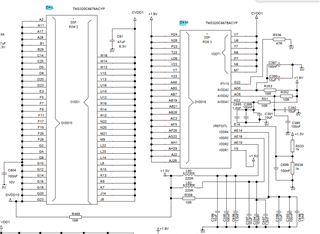
We are using a TMS320C6678 DSP in our design. We do not use the DDR memory and the signals are left open.
Voltage order is okay.
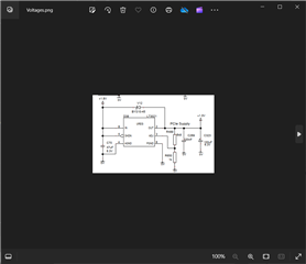
DDRCLKP is connected to +1.8V and DDRCLKN is connected to GND via a 1 kohm resistor.
DVDD15 is connected to +1.5V via a 10 ohm resistor.
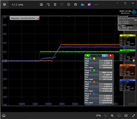
We have noted that on some units DVDD15 starts at +1.5V and after 200ms it drops to +1V and after another 200ms it drops to +0.7V.
The other side of the 10ohm resistor stays at +1.5V.
Not all units behave like this. Do we have a flaw in our DSPs?
Or doesn't this voltage drop matters?

Best Regards

Lars-Olle Arnesson
Blue is DVDD15

  • Lars-Olle Arnesson,

    Good day!

    Feel free. 

    I have notified to hardware experts.

    Regards

    Shankari G

  • Hello Lars,

    Apologies for the delay.  I can't say whether it matters or not, but it does sound like a potential concern in that a non-trivial amount of current seems to be being drawn by the SoC (across the 10 Ohm resistor).  

    Can you confirm that the internal DDR PLL isn't accidentally configured in software - i.e., DDR PLL should be left disabled.

    Can you also try to correlate what happens around the same time the two voltage drops occur (+200 ms, +200 ms).  Is there something in hardware that is turned on?  Or maybe something in software that is activated (again, maybe the PLL?).

    Regards,

    Kyle

  • Hello Kyle
    Thank you for your answer. It isn't visible in the schematic snippet, but our DDRCLK
    is tied to static voltage and ground as described in the datasheet. I have found in your document:
    Hardware design guide for KeyStoneTm I devices, point 6.8.4, that the DDRCLK must have clock signals even if DDR isn't used.
    Can't that be the reason?

    Best regards
    Lars

  • Lars,

    OK, I didn't see that statement initially.  For debug, do you have access to the DDRCLK inputs on existing boards such that you can blue-wire in a clock?

    Thanks,

    Kyle

  • Hello Kyle

    I checked this, but unfortunately I can only reach the negative DDRCLK.

    Best Regards
    Lars

  • Lars,

    This is a bit of a hack, not sure it will do what we want ... With a blue wire on the negative DDRCLK ... can you pipe in a clock waveform and see if that can pass through the PLL (need to enable PLL in software) and help to propagate the DDR clock to the DDR IP, potentially getting the DDR IP into a "known good state"?

    Thanks,
    Kyle

  • Hello Kyle

    Thank you for your patience, we will try that but in the end we will need a redesign.

    One last question, what if we remove the resistor, leaving the DDR interface without any power supply? 
    Will that cause even more problems?

    Thanks and Best Regards
    Lars-Olle Arnesson

  • Lars,

    I don't recommend to remove the DDR I/f power supply (yet).  

    Another angle related to my "blue wire in a clock":  During the PLL initiallization sequence, even with no input clock, I would expect the PLL to generate some number of clock edges that may be sufficient to get the DDR into a known/reset state.  This isn't necessarily guaranteed but would be a useful debug direction.

    Is your software turning on the DDR PLL as a normal part of the boot up?  Can you experiment with enabling the DDR PLL in software ... does that eliminate your mysterious current consumption/voltage drop across the series resistor?  

    Thanks,

    Kyle

  • Hello Kyle and Ambroise
    We don't turn on the PLL in our software. and I'm still waiting for new SW that do turn it on.
    Meanwhile I have done some more tests and the same unit behaves differently at different start ups.

    I have checked the start up voltages to the TI DSP with a more zoomed:


    Red 1.8V, green +1.5V

    And the 1.5V regulator:

    I have also tested to leave the unit on for a while with low DVDD15 (about +0.7V) and the tried to start again. We have very good cooling so it isn't get very hot. But the start up of DVDD15 is very random. Some units does actually start better after warming up.
    How much damage can this cause to the DSP?

    Best Regards
    Lars

  • Lars,  Do you mean blue is 1.5V?  

    Do you have access to JTAG and CCS?  You may be able to program PLL via GEL file running from CCS.

    Regards,
    Kyle

  • Hi Kyle
    Yes, blue is +1.5V, I am sorry for my mistake.
    We have the DSP in the JTAG chain, it is the first component in the chain. Our SW team are working with a new solution that initiate the PLL right now.

    Best Regards
    Lars