This thread has been locked.

If you have a related question, please click the "Ask a related question" button in the top right corner. The newly created question will be automatically linked to this question.

TMS570LC4357 for BLDC control with RESET signals

Part Number: TMS570LC4357

Hello,

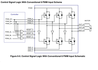
I am trying to configure the ePWM output 1 to 3 on the TMS570LC4357 microcontroller to produce control signals for a BLDC motor. The driver I am using doesn't require high and low complementary signals but rather high and reset signals, as shown in the image. Is it possible to produce this signal directly on the microcontroller? 
  • Hello Serket,

    All our experts for these devices are on Holiday leave until the 27th, so apologies that we will not be able to provide an answer until the back half of next week.

    Best Regards,

    Ralph Jacobi

  • Hi Serket,

    Apologies for the delay in the response.

    My understanding is that, each RESET signal is generating by passing direct and complement PWM's to the OR gate. That means RESET signal will be high whenever either of the input is high- and this keeps the circuit active but if both the inputs are low then RESET signal will becomes zero and it will keep the circuit into RESET.

    So basically, if no PWM waveforms are generating then the output circuit will be in RESET and if any PWM wave is generating then the corresponding RESET will be disabled.

    Is it possible to produce this signal directly on the microcontroller? 

    So as i mentioned the RESET pin just needs to be logic-0 before generating PWM waveforms and it should need to be logic-1 whenever PWM waveforms are generating.

    So, my suggestion would be you can simply use GIO's for this purpose and you can keep the GIO to logic-0 before you generating PWM waveforms and you can keep the GIO to logic-1 after you are generating PWM's.

    So, my suggestion is kept GIO to logic-1 before you are calling "etpwmStartTBCLK" function and kept GIO to logic-0 after you are calling "etpwmStopTBCLK" function.

    --
    Thanks & regards,
    Jagadish.

  • Hello Jagadish,

    Thank you for the answer. Unfortunately, the board was already manufactured and the connections were done directly to the PWM outputs 1, 2, and 3. Is there any way to configure the PWM output B to behave as the driver requires? 

  • Hi Serket,

    In above image, the green color highlighted pins can also be used as GIO functionality, but the red highlighted pin cannot have GIO functionality as it has only one functionality that is PWM output B.

    So just make sure which pin you used for ePWM1B, if you use H3 for ePWM1B then there is no issue you can configure this pin as GIO and can use this pin as RESET signal as i mentioned in my previous comment but if you use D10 as ePWM1B then there is no option it will be always a complement output of ePWM1A and that means it will also generates a complement PWM waveform.

    --
    Thanks & regards,
    Jagadish.