This thread has been locked.

If you have a related question, please click the "Ask a related question" button in the top right corner. The newly created question will be automatically linked to this question.

TDA4VH-Q1: QSGMII Serdes Eye Diagram

Part Number: TDA4VH-Q1
Other Parts Discussed in Thread: TDA4VH

Hi TI Experts,

Customer is working on TDA4VH SDK9.0.

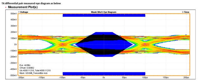
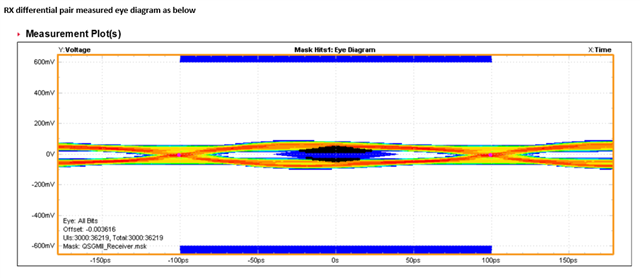
They have finished their customer board recently and started testing their QSGMII serdes eye diagram.

They have found the problem showing that the voltage amplitude could not meet the QSGMII Spec requirement shown below (blue part is the pattern per QSGMII spec).

Based on the above problem, customer may need know the following points, which may help debug this problem.

1: Is it feasible to increase the serdes driver side driving amplitude by serdes register configuration? 

2: What would be the most possible reasons that lead to such issue like lack of signal amplitude?

3: Do we have a layout guideline or recommendation for SGMII and QSGMII serdes interface and routing?  We are confused for the high speed differential AC coupling cap location, it should be near output driver side (tx) or receiver side (rx)? It seems different documents have different arguments.

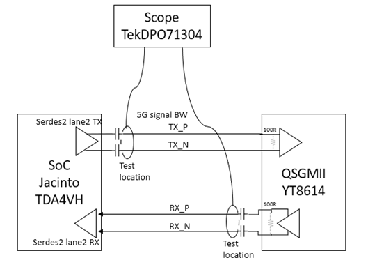
4: We do notice that the QSGMII PHY has a 100ohm resistor terminated between drive and receive differential pairs, does Jacinto serdes has 100ohm resistor terminated internally?

5: What is the differential signal type for serdes TX/RX differential pairs for TDA4VH?  Is it LP-HCSL or CML or other type? We could not find it from the datasheet. In the datasheet it just mentions REF_CLK is HCSL.

6: Currently we use AC coupling cap (0.1uF X7S C0201 6.3V),  do you have some suggestion here as we see the EVM board uses 0.22uF?

Thanks a lot!

Kevin

  • Hi Kevin,

    The eye mask of 200mV and 450mV is correct for QSGMII standards.

    Are they disconnecting the PHY side when measuring on the scope? the scope provides 50ohm termination for the p/n of TX. if they are still connected to PHY then it will result in halving the amplitude with the parallel resistor combination.

  • On the other questions, I will need help from our schematic review team.

  • Hi Shreyas,

    Thanks for your suggestion!

    We have figured root cause of  lack of amplitude for QSGMII TX eye diagram,  there is a calibration failure of O-scope probe accessory,  problem has been fixed by changing a new probe accessary, now the result looks good.

    Could you also help reach to the schematic review team for the below 4 points please?

    1. We are confused for the QSGMII Serdes high speed differential AC coupling capacitor location,  should it near output driver side or receiver side? It seems different document has different arguments.
    2. We do notice that the QSGMII PHY has a 100ohm resister terminated between drive and receive differential pairs,  does Jacinto Serdes has 100ohm Res terminated internally?
    3. What is the differential signal type for Serdes TX/RX differential pairs for Jacinto?  LP-HCSL? Or CML?  Or other type?   We can’t find from datasheet, it just says REF_CLK is HCSL
    4. Currently we use AC coupling cap (0.1uF X7S C0201 6.3V),  do you have some suggestion here as we see the EVM board uses 0.22uF?

    These information are very important for customers' board design.

    Thanks a lot!

    Kevin

  • The location of the AC coupling capacitors should not matter (near source or near load).  Both P and N capacitors should be near each other..  TI uses 0.22uF as it has better performance for higher speed interfaces like QSGMII, PCIe, USB, etc.

  • Hi Robert,

    Thanks a lot for your reply!

    Could you also share some suggestions for the below two points please?

    1. We do notice that the QSGMII PHY has a 100ohm resister terminated between drive and receive differential pairs,  does Jacinto Serdes has 100ohm Res terminated internally?
    2. What is the differential signal type for Serdes TX/RX differential pairs for Jacinto?  LP-HCSL? Or CML?  Or other type?   We can’t find from datasheet, it just says REF_CLK is HCSL

    Thanks a lot!

    Kevin

  • Kevin,

    Currently, I do not have the answer to these. I will have to raise a ticket to the external design team to get this answered.

    How critical are these questions to the customer?

  • Hi Shreyas,

    Thanks for your feedback!

    This is important for customer to understand the different or same signal type AC coupling transition and termination. They are making the final HW design based on TDA4VH. If it is possible, please help raise a ticket to the external team, thanks for your strong help!

    Thanks,

    Kevin  

  • Kevin,

    I have submitted the ticket to Cadence and will respond once they reply to this.

  • Yes, the Torrent PHY has internal termination. The internal termination is 50 ohms to ground single-ended, 
    which will appear as 100 ohm differential when AC coupled.
    The Transmitter is a voltage-mode driver and was developed keeping PCIe specification in mind when driving into a 100ohm
    receiver and not according to signal type.