This thread has been locked.

If you have a related question, please click the "Ask a related question" button in the top right corner. The newly created question will be automatically linked to this question.

AM625: common dtsi

Part Number: AM625
Other Parts Discussed in Thread: SYSCONFIG

Dear Team,

In the AM62x SDK [v9.1], is it necessary to modify the file ..arch/arm/dts/k3-am62x-sk-common.dtsi for a custom design of the SoM?

If modification is required, which node should I start with in the dts file?

Thanks and Regards,

Ravikumar

  • Hi Ravikumar,

    I have taken note of your query, please expect responses in few business days.

    Thanks for your patience.

    Regards,

    Vaibhav

  • Hi Vaibhav 

    Thank you for your response. I hope to receive a specific reply very soon.


    Best Regards,

    Ravikumar

  • Hi Ravikumar,

    So, it depends on your usecase.

    Suppose you need few peripherals allocated/enabled/disabled.

    In this scenario you need to identify the pin muxing for those peripherals and update in the dts file.

    Then proceed to build the dts files via command make linux-dtbs

    Now you can replace this dtb file in the sd card partition root/boot

    Please let me know if you need guidance on setting up/getting pin mux configuration for certain peripherals.

    Thanks,

    Vaibhav

  • Hi Vaibhav,

    Thank you for the information.

    Could you please guide me on how to initialize pin mux configuration for QSPI in the .dts file using the sysconfig tool? Providing an example would be extremely helpful.

    Best Regards,

    Ravikumar  

  • Hi Ravikumar,

    Thanks for your patience.

    SysConfig Tool can be used as medium to have the contents for dts file ready.

    But, on Linux side, SysConfig is a way to see the pinmux tools and configure it on the device tree source file.

    Please see the steps below.

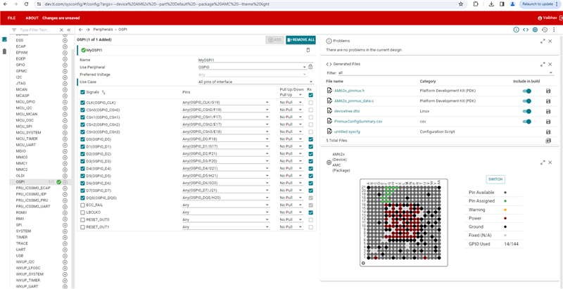
    1. Head over to dev.ti.com/sysconfig and select the part number AM62x

    2. Select OSPI from the left tab as shown in the screenshot below.

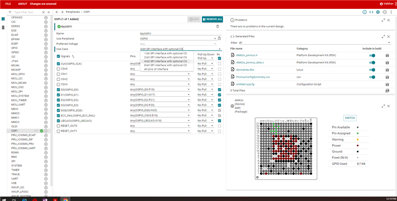
    3. Now, currently OSPI is selected BUT we need QSPI.

    4. From the "usecase" dropdown select 4 pin mode to enable QSPI.

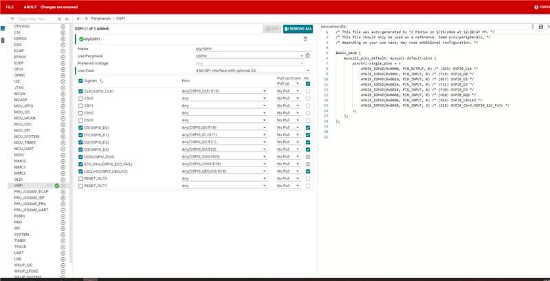
    5. On the right hand window, there is a file devicetree.dtsi

    6. Click open the file and both of us will be on this page.

    7. Now we just need to take the contents of the generated files devicetree.dtsi.

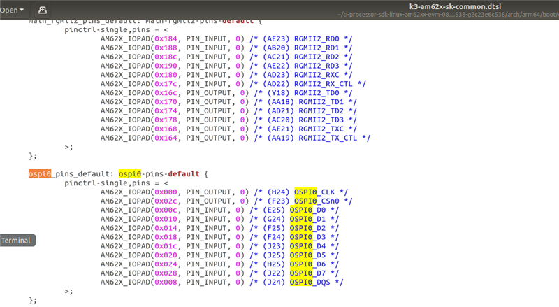
    8. This will be fed into the file named "k3-am62x-sk-common.dtsi"

    NOTE: One thing to keep in mind while adding these pinmux settings to the dtsi file would be to avoid conflicts. For example, a pin assigned for UART should not be used by some other protocol/peripheral. So avoid pinmux conflicts.

    I hope this explanation helps.

    If there is anything else you want me to elaborate, please let me know.

    Regards,

    Vaibhav

  • Hi Ravikumar,

    Please make sure to mark the thread resolved if the above answer helped you.

    Thanks,

    Vaibhav

  • Hi Vaibhav

    Thank you for your helpful updates. I have grasped the SPI configuration use case. I have one more query regarding the aliasing of the OSPI node for SPI0. How can I modify a specific property and its value in the following file: ../../k3-am62x-sk-common.dts?

    &ospi0 {
    	status = "okay";
    	pinctrl-names = "default";
    	pinctrl-0 = <&ospi0_pins_default>;
    
    	flash@0{
    		compatible = "jedec,spi-nor";
    		reg = <0x0>;
    		spi-tx-bus-width = <8>;
    		spi-rx-bus-width = <8>;
    		spi-max-frequency = <25000000>;
    		cdns,tshsl-ns = <60>;
    		cdns,tsd2d-ns = <60>;
    		cdns,tchsh-ns = <60>;
    		cdns,tslch-ns = <60>;
    		cdns,read-delay = <4>;
    		cdns,phy-mode;
    
    		partitions {
    			compatible = "fixed-partitions";
    			#address-cells = <1>;
    			#size-cells = <1>;
    
    			partition@0 {
    				label = "ospi.tiboot3";
    				reg = <0x0 0x80000>;
    			};
    
    			partition@80000 {
    				label = "ospi.tispl";
    				reg = <0x80000 0x200000>;
    			};
    
    			partition@280000 {
    				label = "ospi.u-boot";
    				reg = <0x280000 0x400000>;
    			};
    
    			partition@680000 {
    				label = "ospi.env";
    				reg = <0x680000 0x40000>;
    			};
    
    			partition@6c0000 {
    				label = "ospi.env.backup";
    				reg = <0x6c0000 0x40000>;
    			};
    
    			partition@800000 {
    				label = "ospi.rootfs";
    				reg = <0x800000 0x37c0000>;
    			};
    
    			partition@3fc0000 {
    				label = "ospi.phypattern";
    				reg = <0x3fc0000 0x40000>;
    			};
    		};
    	};
    };


    Best Regards,

    Ravikumar

  • Hi Ravikumar,

    I have noted your query.

    Please expect responses in few business days.

    Thanks for your patience.

    Regards,

    Vaibhav

  • Hi Vaibhav

    Any updates ?


    Best Reagrds,

    Ravikumar 

  • Hi Ravikumar,

    I have added some logs alongside the text file you attached above.

    I have written down the meaning for them and the values you can configure.

    &ospi0 {
    	status = "okay";                            ---> Can be changed to disabled to indicate kernel that OSPI is not configured
    	pinctrl-names = "default";
    	pinctrl-0 = <&ospi0_pins_default>;          ---> Name of the pincontrol which is written under main_pmx
    
    	flash@0{
    		compatible = "jedec,spi-nor";           ---> Stating that the Flash Part is supporting OSPI NOR
    		reg = <0x0>;
    		spi-tx-bus-width = <8>;
    		spi-rx-bus-width = <8>;
    		spi-max-frequency = <25000000>;         ---> maximum operating frequency
    		cdns,tshsl-ns = <60>;                   ---> Delay in nanoseconds for the length that the master mode chip select outputs are de-asserted between transactions
    		cdns,tsd2d-ns = <60>;                   ---> Delay in nanoseconds between one chip select being de-activated and the activation of another.
    		cdns,tchsh-ns = <60>;                   ---> Delay in nanoseconds between last bit of current transaction and deasserting the device chip select (qspi_n_ss_out).
    		cdns,tslch-ns = <60>;                   ---> Delay in nanoseconds between setting qspi_n_ss_out low and first bit transfer.
    		cdns,read-delay = <4>;                  ---> Delay for read capture logic, in clock cycles
    		cdns,phy-mode;
    
    		partitions {
    			compatible = "fixed-partitions";
    			#address-cells = <1>;
    			#size-cells = <1>;
    
    			partition@0 {
    				label = "ospi.tiboot3";
    				reg = <0x0 0x80000>;
    			};
    
    			partition@80000 {
    				label = "ospi.tispl";
    				reg = <0x80000 0x200000>;
    			};
    
    			partition@280000 {
    				label = "ospi.u-boot";
    				reg = <0x280000 0x400000>;
    			};
    
    			partition@680000 {
    				label = "ospi.env";
    				reg = <0x680000 0x40000>;
    			};
    
    			partition@6c0000 {
    				label = "ospi.env.backup";
    				reg = <0x6c0000 0x40000>;
    			};
    
    			partition@800000 {
    				label = "ospi.rootfs";
    				reg = <0x800000 0x37c0000>;
    			};
    
    			partition@3fc0000 {
    				label = "ospi.phypattern";
    				reg = <0x3fc0000 0x40000>;
    			};
    		};
    	};
    };

    I hope this helps.

    A detailed explanation can be found here: www.kernel.org/.../cadence-quadspi.txt

    Looking forward to your response.

    Regards,

    Vaibhav

  • Hi Vaibhav

    Thanks for you meaningful inputs and I will go through it.

    Best Regards,

    Ravikumar

  • Hi Ravikumar,

    Happy to help Slight smile

    Looking forward to your response.

    Regards,

    Vaibhav

  • Hi Vaibhav Slight smile

    I vividly understood the meanings of the properties, but I have a tiny clarification on 'spi-tx-bus-width = <8>' and 'spi-rx-bus-width = <8>'. Do these values also change for QSPI?


    Best Regards,

    Ravikumar

  • Hi Ravikumar,

    I will check about this internally.

    Post discussion I will be able to put out a response here.

    Please allow me few business days to get back on this.

    Thanks for your patience.

    Regards,

    Vaibhav

  • Hi Vaibhav 


    Thanks for quick response, & i hope to get your reply soon

    Best Regards,

    Ravikumar

  • Hi Vaibhav 

    Any updates?

    Best Regards,

    Ravikumar

  • Hi Ravikumar,

    I am still looking into this, most likely it would be 4 instead of 8.

    But let me confirm on this, also this thread missed my attention as once the thread resolved icon was clicked the thread kind of closed at our end.

    I will make sure to reply to your question.

    Please allow me sometime.

    Thanks,

    Vaibhav

  • HI Vaibhav 

    I am still looking into this, most likely it would be 4 instead of 8:
             I too also not sure about this value. Please confirm me..

    Specifically Which value i gonna use for QSPI initialization properties?


    Best Regards,

    Ravikumar

  • Hello Ravikumar,

    Since you want to use QSPI which is basically Quad SPI, I believe we need to go for the value 4 for both tx and rx bus width.

    So essentially these two values define the number of MISO and MOSI lines. Please find my explanation below.


    spi-tx-bus-width - (optional) The bus width(number of data wires) that used for MOSI. Defaults to 1 if not present.


    spi-rx-bus-width - (optional) The bus width(number of data wires) that used for MISO. Defaults to 1 if not present.


    So a value of 4 should suffice.

    I hope this helps.

    Thanks,

    Vaibhav

  • Hi Vaibhav

    Thanks for quick response with clarification & I'll use same value.


    Best Regards,

    Ravikumar

  • Hello Ravikumar,

    Happy to help Slight smile

    Regards,

    Vaibhav