Other Parts Discussed in Thread: TDA4VH
Hi TI Experts,
Customer is working on TDA4VH SDK9.1.
I have previously asked a related question in the below thread.
We have made it work on USB2.0 with the below code commands.
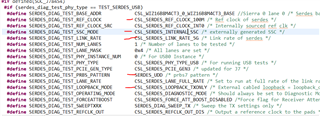
Force to output Test Packet for Eye Diagram Test
devmem2 0x06010484 w 0x40000000
Force to output J_STATE
devmem2 0x06010480 w 0x000000A0
Force to output K_STATE
devmem2 0x06010080 w 0x00000004
Force to output SE0 (host) / NAK(device)
devmem2 0x06010484 w 0x30000000
We previously thought for the USB3.0, the code command should be the same, so we close the thread.
However, recently when we look at the details of the above register address, we found that the description is just for USB2.0, but not for the USB3.0.
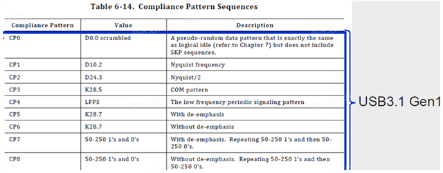
Also, we could not find the register address related to the CP0 & CP1 shown below in the USB3.0 compliance pattern sequence.
Could you help to provide the corresponding commands needed to test the following features in USB3.0 on TDA4VH please?
1: Force to output Test Packet for Eye Diagram Test
2: Force to output J_STATE
3: Force to output K_STATE
4: Force to output SE0 (host) / NAK(device)
5: CP0 & CP1 Test (any command needed to switch from CP0 to CP1 test?)
We have found some general test steps of USB3.0 standard shown below for CP0 & CP1 Test.
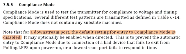
May I know is there a suggested configuration or command that could make TDA4VH enable USB3.0 Compliance mode?
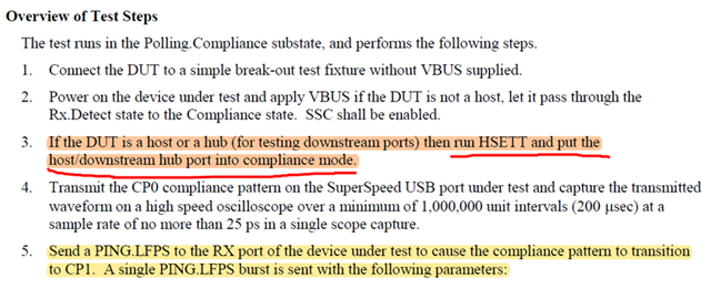
The reason to ask is that, according to the USB3.0 standard it mentions that, as a host, the compliance mode is disabled by default, and it needs SOC to enable it.
Many Thanks!
Kevin