Part Number: PROCESSOR-SDK-AM62A
Other Parts Discussed in Thread: SYSCONFIG
Hello TI,
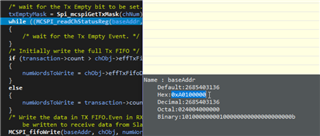
I'm running a program on the MCU R5 core that gets booted by the kernel. The program's goal is to access the Main domain's SPI0 from the MCU domain. But when calling the MCSPI_transfer api, it doesn't return and hangs. Using the XDS110 debugger, I found it's waiting for the Tx Empty bit to be set.
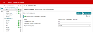
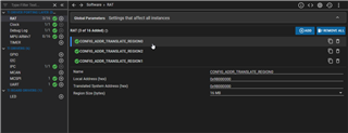
I followed the steps from the link below to make sure the syscfg file is setup correctly. The dts is also updated to ensure there's no instances of main_spi0 defined and no spi0 pins are configured. The dts does however use spi1 so I left that defined. Lastly I configured the RAT so that it covers all of the MCSPI physical addresses.
Is there anything else I'm missing with configuration? I've ran similar SPI code using the mcspi loopback test example and confirmed the MCU SPI is working.
Thanks,
Joseph
/**
* These arguments were used when this file was generated. They will be automatically applied on subsequent loads
* via the GUI or CLI. Run CLI with '--help' for additional information on how to override these arguments.
* @cliArgs --device "AM62Ax" --package "AMB" --part "Default" --context "mcu-r5fss0-0" --product "MCU_PLUS_SDK_AM62Ax@09.00.00"
* @versions {"tool":"1.18.0+3266"}
*/
/**
* Import the modules used in this configuration.
*/
const ipc = scripting.addModule("/drivers/ipc/ipc");
const mcspi = scripting.addModule("/drivers/mcspi/mcspi", {}, false);
const mcspi1 = mcspi.addInstance();
const addr_translate = scripting.addModule("/kernel/dpl/addr_translate", {}, false);
const addr_translate1 = addr_translate.addInstance();
const debug_log = scripting.addModule("/kernel/dpl/debug_log");
const mpu_armv7 = scripting.addModule("/kernel/dpl/mpu_armv7", {}, false);
const mpu_armv71 = mpu_armv7.addInstance();
const mpu_armv72 = mpu_armv7.addInstance();
const mpu_armv73 = mpu_armv7.addInstance();
const mpu_armv74 = mpu_armv7.addInstance();
const mpu_armv75 = mpu_armv7.addInstance();
const mpu_armv76 = mpu_armv7.addInstance();
/**
* Write custom configuration values to the imported modules.
*/
ipc.r5fss0_0 = "NONE";
ipc.c75ss0_0 = "NONE";
mcspi1.$name = "CONFIG_MCSPI0";
mcspi1.useMcuDomainPeripherals = false;
mcspi1.intrEnable = "POLLED";
mcspi1.mode = "MULTI_MASTER";
mcspi1.SPI.$assign = "SPI0";
mcspi1.mcspiChannel.create(3);
mcspi1.mcspiChannel[0].$name = "CONFIG_MCSPI_CH0";
mcspi1.mcspiChannel[0].CSn.$assign = "SPI0_CS0";
mcspi1.mcspiChannel[1].$name = "CONFIG_MCSPI_CH1";
mcspi1.mcspiChannel[1].CSn.$assign = "SPI0_CS1";
mcspi1.mcspiChannel[2].$name = "CONFIG_MCSPI_CH2";
mcspi1.mcspiChannel[2].CSn.$assign = "UART0_RTSn";
addr_translate1.$name = "CONFIG_ADDR_TRANSLATE_REGION0";
addr_translate1.localAddr = 0xA0000000;
addr_translate1.systemAddr = 0x20000000;
debug_log.enableUartLog = true;
debug_log.enableMemLog = true;
debug_log.uartLog.$name = "CONFIG_UART0";
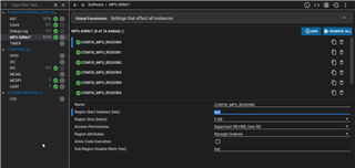
mpu_armv71.$name = "CONFIG_MPU_REGION0";
mpu_armv71.size = 31;
mpu_armv71.attributes = "Device";
mpu_armv71.accessPermissions = "Supervisor RD+WR, User RD";
mpu_armv71.allowExecute = false;
mpu_armv72.$name = "CONFIG_MPU_REGION1";
mpu_armv72.size = 15;
mpu_armv72.accessPermissions = "Supervisor RD+WR, User RD";
mpu_armv73.$name = "CONFIG_MPU_REGION2";
mpu_armv73.baseAddr = 0x41010000;
mpu_armv73.size = 15;
mpu_armv73.accessPermissions = "Supervisor RD+WR, User RD";
mpu_armv74.$name = "CONFIG_MPU_REGION3";
mpu_armv74.accessPermissions = "Supervisor RD+WR, User RD";
mpu_armv74.baseAddr = 0x79100000;
mpu_armv74.size = 19;
mpu_armv75.$name = "CONFIG_MPU_REGION4";
mpu_armv75.baseAddr = 0x60000000;
mpu_armv75.size = 28;
mpu_armv75.accessPermissions = "Supervisor RD, User RD";
mpu_armv76.$name = "CONFIG_MPU_REGION5";
mpu_armv76.baseAddr = 0x80000000;
mpu_armv76.size = 31;
/**
* Pinmux solution for unlocked pins/peripherals. This ensures that minor changes to the automatic solver in a future
* version of the tool will not impact the pinmux you originally saw. These lines can be completely deleted in order to
* re-solve from scratch.
*/
mcspi1.SPI.CLK.$suggestSolution = "SPI0_CLK";
mcspi1.SPI.D0.$suggestSolution = "SPI0_D0";
mcspi1.SPI.D1.$suggestSolution = "SPI0_D1";
debug_log.uartLog.MCU_UART.$suggestSolution = "MCU_USART0";
debug_log.uartLog.MCU_UART.RXD.$suggestSolution = "MCU_UART0_RXD";
debug_log.uartLog.MCU_UART.TXD.$suggestSolution = "MCU_UART0_TXD";