This thread has been locked.

If you have a related question, please click the "Ask a related question" button in the top right corner. The newly created question will be automatically linked to this question.

DRA829V: OTP programming on HS device

Part Number: DRA829V
Other Parts Discussed in Thread: DRA829

Hello experts,

We have recently received variants of our custom board equipped with HS SoC:s.

Can you please point me in the right direction on how to proceed with OTP programming
(public key, vid:pid, serial number etc), and how to build the correct files needed for
a secure boot.

This is mainly for factory, but we want to try it out on a key-pair of our own, before we
send away files to be signed.

What we want to achieve:

  • Burn public key, vid:pid and serial# to OTP
  • On boot, validate the boot files (tiboot3.bin, sysfw, tispl.bin, u-boot.img) that have been
    signed with the private key
  • From U-Boot and onwards we will use another key-pair to secure kernel and dtb:s.

We are using yocto to build. Current versions are U-Boot 2023.04, Linux 6.1.69.

In my deploy-folder, I have the following binaries:

-rw-r--r-- 2 bomellberg bomellberg 268978 Jan 31 14:45 sysfw-j721e-gp-evm.itb
-rw-r--r-- 2 bomellberg bomellberg 278254 Jan 31 14:45 sysfw-j721e_sr1_1-hs-evm.itb
-rw-r--r-- 2 bomellberg bomellberg 269718 Jan 31 14:45 sysfw-j721e_sr2-hs-fs-evm.itb

-rw-r--r-- 2 bomellberg bomellberg 273257 Jan 31 14:45 tiboot3-j721e-gp-evm.bin
-rw-r--r-- 2 bomellberg bomellberg 274031 Jan 31 14:45 tiboot3-j721e_sr1_1-hs-evm.bin
-rw-r--r-- 2 bomellberg bomellberg 274032 Jan 31 14:45 tiboot3-j721e_sr2-hs-fs-evm.bin

-rw-r--r-- 2 bomellberg bomellberg 1021907 Jan 31 14:46 tispl.bin-asp3-2023.04+git999-r0

-rw-r--r-- 2 bomellberg bomellberg   1328683 Jan 31 14:46 u-boot-asp3-2023.04+git999-r0.img

My binman-file has these relevant file references:

  • keyfile = "custMpk.pem"
  • filename = "ti-sysfw/ti-fs-firmware-j721e_sr1_1-hs-cert.bin"
  • filename = "ti-sysfw/ti-fs-firmware-j721e_sr1_1-hs-enc.bin"
  • filename = "ti-sysfw/ti-fs-firmware-j721e_sr2-hs-fs-cert.bin"
  • filename = "ti-sysfw/ti-fs-firmware-j721e_sr2-hs-fs-enc.bin"
I have downloaded the RTOS PDK where I can see references to keywriter, but it is very
difficult to understand how to get it all working.
Best regards,
/Bo

  • Hi Bo,

    Please review the PDK OTP KEYWRITER and the TIFS Key Writer sections in our SDK documentation before you proceed further.

    I recommend that you start out the first test binary from the keywriter test binaries.

    Please note that KeyWriter images are generated using the RTOS SDK, and has no bearing with Yocto / OE build flow. 

    The listed TIFS binaries have no bearing with KeyWriter itself, they are regular boot binaries on HS-FS or HS-SE TIDK (TI Dummy Key) devices.

    regards

    Suman

  • Thanks Suman,

    I have successfully built the keywriter_img_j721e_release.tiimage binary using the TI default settings. What utility should I use to get it onto the R5-core that it should run on, and then actually run it?

    Since this will be done in factory, it needs to be super simple to administer.

    Regards,

    /Bo

  • Hi Bo,

    The file keywriter_img_j721e_release.tiimage is like a bootloader binary. You can use any of your peripheral boot-modes, treat this binary as you would a tiboot3.bin (rename it as such if using SDCard/eMMC, or flash in the same partition as expected for a bootloader binary).

    I do recommend that you use the first binary generated from the steps in OTP KeyWriter Validation to program the MSV. Please do capture the logs from both the MCU UART as well as the WKUP UART, as they provide proof of the KeyWriter process. Please refer to the OTP KeyWriter Logs for an example reference log.

    Please see the Jacinto7 HS Device Flashing Solution AppNote. A lot of it depends on your factory flow (like pre-flashed OSPI Flash or eMMC etc).

    regards

    Suman

  • Hi Suman,

    At this point I just want to understand the process, and how to streamline it for our purposes (and the factory).

    I have tried to send the built keywriter_img_j721e_release.tiimage via dfu to my normal GP device. There was no output from any of the debug ports. Normally I see the standard boot log on one port and the "0x710002 0xB10004 0x4003007 0x4400906 0x71000B 0xB10004" on the other port. They are both silent.

    I then tried it on one of our secure devices but there was no output there either. Am I missing what debug port to look at?

    Regards,

    /Bo

  • Hi Bo,

    I have tried to send the built keywriter_img_j721e_release.tiimage via dfu to my normal GP device.

    The KeyWriter image is only meant to run on HS-FS devices. A GP device does not have any efuses at all.

    I am not sure what you are trying to validate running this on a GP device. Please note that the KeyWriter TIFS binary is signed with the TI MPK key, which can't be authenticated on a GP device as well. 

    I then tried it on one of our secure devices but there was no output there either. Am I missing what debug port to look at?

    The KeyWriter images are meant to provide output on the MCU (KeyWriter application) and WKUP UART (KeyWriter TIFS binary) respectively. Are these UARTs pinned out and made available for your custom board?

    Normally I see the standard boot log on one port and the "0x710002 0xB10004 0x4003007 0x4400906 0x71000B 0xB10004" on the other port.

    This suggests that you do have a Wkup UART. You will see similar data initial with the KeyWriter image as well.

    I then tried it on one of our secure devices but there was no output there either.

    If you have JTAG access, you should be able to connect to the MCU R5F core and see where the execution is stuck at. 

    regards

    Suman

  • Hi Suman,

    Trying it on the GP device was just to see if I could get any debug info at all.

    The KeyWriter images are meant to provide output on the MCU (KeyWriter application) and WKUP UART (KeyWriter TIFS binary) respectively. Are these UARTs pinned out and made available for your custom board?

    I think this is where I fail. I need to map my ports in the keywriter application, as it controls these regardless of what I have done in the dts-files in the Yocto-tree earlier.

    This suggests that you do have a Wkup UART. You will see similar data initial with the KeyWriter image as well.

    I will try to get this kind of output.

    Do you have any hint on how to set the proper uart-ports for the keywriter application?

    My ports are available at:

    mcu_uart0 (@40a00000) - on ball H27 and H26
    wkup_uart0 (@42300000) - on ball J29 and J28

    Regards,

    /Bo

  • Hi Bo,

    Trying it on the GP device was just to see if I could get any debug info at all.

    Are you looking for debug info from the KeyWriter application itself or TIFS? The KeyWriter TIFS binary is signed with the TI MPK, which doesn't exist on GP devices. IIRC, the first traces on the KeyWriter application happens after TIFS is booted, and you won't be able to boot the KeyWriter TIFS binary on a GP device.

    I think this is where I fail. I need to map my ports in the keywriter application, as it controls these regardless of what I have done in the dts-files in the Yocto-tree earlier.

    KeyWriter image is a standalone bare-metal application on MCU1_0. It has no bearing with Linux dts-files or Yocto tree.

    Do you have any hint on how to set the proper uart-ports for the keywriter application?

    My ports are available at:

    mcu_uart0 (@40a00000) - on ball H27 and H26
    wkup_uart0 (@42300000) - on ball J29 and J28

    The TI SDK also uses MCU UART and WKUP UARTs, and the KeyWriter application relies on the Board library for the necessary pinmux configuration. If these are the same padconfigs used as TI EVM, then this should be fine.

    I recommend that you run a simple PDK application on MCU1_0 to verify your GP board first.

    regards

    Suman

  • Hi Suman,

    I'm trying to get something up'n'running in the mcu1_0 cpu. I have compiled the UART_baremetal_Test with my changes for the board-cfg. The problem is, the core is not even showing on sysfs, so I can't fire it up from Linux:

    root@AS-3-P-BEEFF1:~# ls -al /sys/class/remoteproc/
    total 0
    drwxr-xr-x  2 root root 0 Feb  9 14:46 .
    drwxr-xr-x 77 root root 0 Feb  9 14:45 ..
    lrwxrwxrwx  1 root root 0 Feb  9 14:46 remoteproc0 -> ../../devices/platform/bus@100000/bus@100000:r5fss@5c00000/5c00000.r5f/remoteproc/remoteproc0
    lrwxrwxrwx  1 root root 0 Feb  9 14:46 remoteproc1 -> ../../devices/platform/bus@100000/bus@100000:r5fss@5c00000/5d00000.r5f/remoteproc/remoteproc1
    lrwxrwxrwx  1 root root 0 Feb  9 14:46 remoteproc10 -> ../../devices/platform/bus@100000/b100000.icssg/b134000.pru/remoteproc/remoteproc10
    lrwxrwxrwx  1 root root 0 Feb  9 14:46 remoteproc11 -> ../../devices/platform/bus@100000/b100000.icssg/b104000.rtu/remoteproc/remoteproc11
    lrwxrwxrwx  1 root root 0 Feb  9 14:46 remoteproc12 -> ../../devices/platform/bus@100000/b100000.icssg/b10a000.txpru/remoteproc/remoteproc12
    lrwxrwxrwx  1 root root 0 Feb  9 14:46 remoteproc13 -> ../../devices/platform/bus@100000/b100000.icssg/b138000.pru/remoteproc/remoteproc13
    lrwxrwxrwx  1 root root 0 Feb  9 14:46 remoteproc14 -> ../../devices/platform/bus@100000/b100000.icssg/b106000.rtu/remoteproc/remoteproc14
    lrwxrwxrwx  1 root root 0 Feb  9 14:46 remoteproc15 -> ../../devices/platform/bus@100000/b100000.icssg/b10c000.txpru/remoteproc/remoteproc15
    lrwxrwxrwx  1 root root 0 Feb  9 14:46 remoteproc2 -> ../../devices/platform/bus@100000/bus@100000:r5fss@5e00000/5e00000.r5f/remoteproc/remoteproc2
    lrwxrwxrwx  1 root root 0 Feb  9 14:46 remoteproc3 -> ../../devices/platform/bus@100000/bus@100000:r5fss@5e00000/5f00000.r5f/remoteproc/remoteproc3
    lrwxrwxrwx  1 root root 0 Feb  9 14:46 remoteproc4 -> ../../devices/platform/bus@100000/b000000.icssg/b034000.pru/remoteproc/remoteproc4
    lrwxrwxrwx  1 root root 0 Feb  9 14:46 remoteproc5 -> ../../devices/platform/bus@100000/b000000.icssg/b004000.rtu/remoteproc/remoteproc5
    lrwxrwxrwx  1 root root 0 Feb  9 14:46 remoteproc6 -> ../../devices/platform/bus@100000/b000000.icssg/b00a000.txpru/remoteproc/remoteproc6
    lrwxrwxrwx  1 root root 0 Feb  9 14:46 remoteproc7 -> ../../devices/platform/bus@100000/b000000.icssg/b038000.pru/remoteproc/remoteproc7
    lrwxrwxrwx  1 root root 0 Feb  9 14:46 remoteproc8 -> ../../devices/platform/bus@100000/b000000.icssg/b006000.rtu/remoteproc/remoteproc8
    lrwxrwxrwx  1 root root 0 Feb  9 14:46 remoteproc9 -> ../../devices/platform/bus@100000/b000000.icssg/b00c000.txpru/remoteproc/remoteproc9
    

    dmesg shows some errors for the remoteproc:

    root@AS-3-P-BEEFF1:~# dmesg | grep remote
    [    0.148147] remoteproc remoteproc0: 41000000.r5f is available
    [    0.148182] remoteproc remoteproc0: attaching to 41000000.r5f
    [    0.148290] remoteproc remoteproc0: can't attach to rproc 41000000.r5f: -16
    [    0.148437] remoteproc remoteproc0: releasing 41000000.r5f
    [    0.149966] platform 5c00000.r5f: configured R5F for remoteproc mode
    [    0.150657] remoteproc remoteproc0: 5c00000.r5f is available
    [    0.150742] remoteproc remoteproc0: Direct firmware load for j7-main-r5f0_0-fw failed with error -2
    [    0.150749] remoteproc remoteproc0: powering up 5c00000.r5f
    [    0.150764] remoteproc remoteproc0: Direct firmware load for j7-main-r5f0_0-fw failed with error -2
    [    0.150768] remoteproc remoteproc0: request_firmware failed: -2
    [    0.150918] platform 5d00000.r5f: configured R5F for remoteproc mode
    [    0.151544] remoteproc remoteproc1: 5d00000.r5f is available
    [    0.151594] remoteproc remoteproc1: Direct firmware load for j7-main-r5f0_1-fw failed with error -2
    [    0.151599] remoteproc remoteproc1: powering up 5d00000.r5f
    [    0.151614] remoteproc remoteproc1: Direct firmware load for j7-main-r5f0_1-fw failed with error -2
    [    0.151618] remoteproc remoteproc1: request_firmware failed: -2
    [    0.152765] platform 5e00000.r5f: configured R5F for remoteproc mode
    [    0.153417] remoteproc remoteproc2: 5e00000.r5f is available
    [    0.153481] remoteproc remoteproc2: Direct firmware load for j7-main-r5f1_0-fw failed with error -2
    [    0.153487] remoteproc remoteproc2: powering up 5e00000.r5f
    [    0.153503] remoteproc remoteproc2: Direct firmware load for j7-main-r5f1_0-fw failed with error -2
    [    0.153507] remoteproc remoteproc2: request_firmware failed: -2
    [    0.153725] platform 5f00000.r5f: configured R5F for remoteproc mode
    [    0.154342] remoteproc remoteproc3: 5f00000.r5f is available
    [    0.154394] remoteproc remoteproc3: Direct firmware load for j7-main-r5f1_1-fw failed with error -2
    [    0.154399] remoteproc remoteproc3: powering up 5f00000.r5f
    [    0.154414] remoteproc remoteproc3: Direct firmware load for j7-main-r5f1_1-fw failed with error -2
    [    0.154417] remoteproc remoteproc3: request_firmware failed: -2
    [    6.002138] remoteproc remoteproc4: b034000.pru is available
    [    6.004516] remoteproc remoteproc5: b004000.rtu is available
    [    6.011531] remoteproc remoteproc6: b00a000.txpru is available
    [    6.011777] remoteproc remoteproc7: b038000.pru is available
    [    6.011920] remoteproc remoteproc8: b006000.rtu is available
    [    6.015804] remoteproc remoteproc9: b00c000.txpru is available
    [    6.016057] remoteproc remoteproc10: b134000.pru is available
    [    6.031255] remoteproc remoteproc11: b104000.rtu is available
    [    6.032748] remoteproc remoteproc12: b10a000.txpru is available
    [    6.032959] remoteproc remoteproc13: b138000.pru is available
    [    6.033098] remoteproc remoteproc14: b106000.rtu is available
    [    6.033238] remoteproc remoteproc15: b10c000.txpru is available
    

    What do I need to get the mcu1_0 available?

    Regards,

    /Bo

  • Hi Bo,

    Please keep the discussion streamlined to the original thread title/issue.

    Please file a new ticket for this unrelated boot issue.

    Is there anything open on your original KeyWriter question?

    regards

    Suman

  • Hi Suman,

    You told me to debug using another app, which I have compiled with the pdk (not Yocto). The problem is to get it running in the mcu1_0 since that CPU is not available.

    Anyway, I found an old thread where you suggested building the k3_r5_remoteproc it as modules and now it has popped up.

    I'll continue the work on Monday 

    Regards,

    /Bo

  • Hi Bo,

    You told me to debug using another app, which I have compiled with the pdk (not Yocto). The problem is to get it running in the mcu1_0 since that CPU is not available.

    The suggestion was mainly to vet/ensure that your MCU and WkUP UARTs are functional, and that portion is not related to KeyWriter.

    You cannot use UART_baremetal_Test firmware image with the Linux flow. Please use a firmware image that is running an RTOS and a SciServer. You can use the ipc_echo_testb_freertos (default firmware image that we use in our SDK) with SPL/U-Boot flow or the sciserver_testapp_freertos image with SBL bootflow. Anyway, this is outside the scope of this current thread.

    I have already responded that it is not possible to run KeyWriter image on a GP device.

    regards

    Suman

  • Hi Suman,

    The suggestion was mainly to vet/ensure that your MCU and WkUP UARTs are functional, and that portion is not related to KeyWriter.

    You cannot use UART_baremetal_Test firmware image with the Linux flow. Please use a firmware image that is running an RTOS and a SciServer. You can use the ipc_echo_testb_freertos (default firmware image that we use in our SDK) with SPL/U-Boot flow

    Thanks, I will use the ipc_echo_testb_freertos app to verify MCU and WKUP UART by loading it from U-Boot.

    I have already responded that it is not possible to run KeyWriter image on a GP device.

    Understood. I have several HS-devices to test with.

    Regards,

    /Bo

  • Hi Bo,

    Do you need any further clarifications on the KeyWriter topic itself, or can I consider this resolved?

    regards

    Suman

  • Hi Suman,

    I have yet to see evidence of output from the keywriter application so this is by no means resolved.

    /Bo

  • Hi Bo,

    I have yet to see evidence of output from the keywriter application so this is by no means resolved.

    OK. And you can only do that on a HS-FS device, not on a GP device. I recommend that you ensure that your HS-FS sample boards boots fine first similar to the GP board (to ensure that there are no issues with h/w soldering) before you attempt the KeyWriter.

    KeyWriter is verified and proven on our side, and the SDK includes reference logs as well as I mentioned in a previous response.

    regards

    Suman

  • Hi Suman,

    Yes, the device is connected and running as fine as the GP devices. We are flashing the four boot-files to qspi-flash using dfu and rootfs including kernel to eMMC. All is working as expected. I am still struggling to get output from the MCU UART though, before I move on to the keywriter. The only this that annoys me is that I still get these prints when booting:

    Trying to boot from SPI
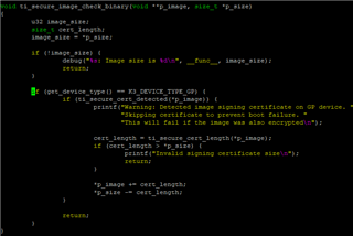
    Warning: Detected image signing certificate on GP device. Skipping certificate to prevent boot failure. This will fail if the image was also encrypted
    Warning: Detected image signing certificate on GP device. Skipping certificate to prevent boot failure. This will fail if the image was also encrypted
    Warning: Detected image signing certificate on GP device. Skipping certificate to prevent boot failure. This will fail if the image was also encrypted
    Warning: Detected image signing certificate on GP device. Skipping certificate to prevent boot failure. This will fail if the image was also encrypted
    Warning: Detected image signing certificate on GP device. Skipping certificate to prevent boot failure. This will fail if the image was also encrypted
    Loading Environment from nowhere... OK
    Starting ATF on ARM64 core...
    

    Which would suggest that my HS-device in fact is a GP device but I suspect it is a general debug-print.

    Other than that, could you please confirm that the follow steps is a valid way forward:

    1. In the pdk, change the board config to match our setup of mcu_uart0.
    (file src/j721e_evm/include/board_cfg.h):

    /* Default pinmux configuration of UART Tx pin used by ROM/SBL */
    #define BOARD_MCU_UART_TX_PINMUX_VAL                    (PIN_MODE(2U) | ((PIN_PULL_DISABLE) & \
                                                             (~PIN_PULL_DIRECTION & ~PIN_INPUT_ENABLE)))
    #define BOARD_MCU_UART_TX_PINMUX_ADDR                   (BOARD_WKUP_PMUX_CTRL_ADDR + PIN_WKUP_GPIO0_10)
    #define BOARD_MCU_UART_TX_LOCK_KICK_ADDR                (CSL_WKUP_CTRL_MMR0_CFG0_BASE + \
                                                             CSL_WKUP_CTRL_MMR_CFG0_LOCK7_KICK0)

    2. With that change, compile the ipc_echo_testb_freertos application
    3. In the Yocto-build system, in binman.dtsi, point to the above application:
    	ti-dm {
    		filename = "ti-dm.bin";
    		blob-ext {
    			filename = "/home/bomellberg/se3linux/ti-processor-sdk-rtos-j721e-evm-09_01_00_06/pdk_jacinto_09_01_00_22/packages/ti/binary/ipc_echo_testb_freertos/bin/j721e_evm/ipc_echo_testb_freertos_mcu1_0_release_strip.xer5f";
    		};
    	};
    
    4. Boot the system with the new files and expect output on the mcu_uart0 port.
    When the above is done, I can move on to the keywriter application. But first I need evidence that I have configured the mcu_uart0 correctly, otherwise I am a bit in blind.
    Regards,
    /Bo
  • Hi Bo,

    I am still struggling to get output from the MCU UART though,

    Are you using SPL or SBL? Note that the Linux SPL doesn't use MCU UART, all the stages directly use the MAIN UART only.

    I will get back to you tomorrow on the remaining items.

    regards

    Suman

  • Hi Suman,

    Are you using SPL or SBL? Note that the Linux SPL doesn't use MCU UART, all the stages directly use the MAIN UART only.

    We are using SPL.

    Regards,

    /Bo

  • Hi Bo,

    Which would suggest that my HS-device in fact is a GP device but I suspect it is a general debug-print.

    Indeed, this is a general debug print. We have unified our U-Boot builds between GP and HS variants, and so you do see these traces on a GP device to ignore the certificates.

    1. In the pdk, change the board config to match our setup of mcu_uart0.
    (file src/j721e_evm/include/board_cfg.h):

    Are you using a different pad configuration compared to our TI EVM? The ROM UART boot typically expects the usage of specific pads.

    2. With that change, compile the ipc_echo_testb_freertos application

    The ipc_echo_testb_freertos application for Linux doesn't use MCU UART at all.

    We are using SPL.

    You will need a SBL flow to leverage the MCU UART.

    Please see this new Application Note UART Log Debug System on Jacinto 7 SoC for UART adjustments.

    regards

    Suman

  • Hi Suman,

    Indeed, this is a general debug print. We have unified our U-Boot builds between GP and HS variants, and so you do see these traces on a GP device to ignore the certificates.

    But this was run on one of my HS devices. Does this mean that the device is in fact NOT an HS device?

    Are you using a different pad configuration compared to our TI EVM? The ROM UART boot typically expects the usage of specific pads.

    Yes. mcu_uart0 is located at pads H26, H27 - mode 2.

    The ipc_echo_testb_freertos application for Linux doesn't use MCU UART at all.

    Got it Thanks.

    Please see this new Application Note UART Log Debug System on Jacinto 7 SoC for UART adjustments.

    Great. Thank you.

    Regards,

    /Bo

  • Hi Bo,

    But this was run on one of my HS devices. Does this mean that the device is in fact NOT an HS device?

    You must have run this on a HS-FS device. The SDK flow is built around the concept of running a HS-SE equivalent images on a HS-FS device with the GP-like benefits to skip the authentication etc. You will not see those traces on a HS-SE device.

    Yes. mcu_uart0 is located at pads H26, H27 - mode 2.

    OK. Isn't UART boot a method supported by your board at all - or you are relying on WKUP UART for UART boot?

    G29 and H28 are the required pins to be used to support MCU UART Boot.

    regards

    Suman

  • Hi Suman,

    You must have run this on a HS-FS device.

    OK, thanks. Since we haven't written any keys yet, it is definately NOT an HS-SE device. But I was puzzled by the print debug saying "GP device".

    OK. Isn't UART boot a method supported by your board at all - or you are relying on WKUP UART for UART boot?

    G29 and H28 are the required pins to be used to support MCU UART Boot.

    No, we haven't made possible to use UART boot. Only QSPI (normal boot) and USB (dfu) are implemented in hardware as bootstrapping options.

    Can you confirm if it is possible or not to bind mcu_uart0 to H26 H27 and still be able to perform OTP programming.

    Regards,

    /Bo

  • Hi Bo,

    OK, thanks. Since we haven't written any keys yet, it is definately NOT an HS-SE device. But I was puzzled by the print debug saying "GP device".

    I looked through the code, and this error is definitely generated on a GP device only.

    The get_device_type() defined in <U-Boot>/arch/arm/mach-k3/common.c will not return TYPE_GP if it is not a GP device.

    Can you confirm if it is possible or not to bind mcu_uart0 to H26 H27 and still be able to perform OTP programming.

    ROM is looking for these pins only for UART Boot. This just means you cannot run KeyWriter using UART boot-mode. UART boot-mode is the most common to easily identify the device as GP or HS-FS or HS-SE and to identify the SoC UID for JTAG unlocking without any software. You have to rely on s/w now to retrieve these, and need to rely on your QSPI or USB boot-modes for KeyWriter.

    You need to ensure your PinMux configuration as you already mentioned.

    regards

    Suman

    PS: I am out on vacation early next week, so will not provide any responses until Thu.

  • Hi Suman,

    Thank you for diving into the code. After contacting TI about our HS-samples, it is confirmed that those are NOT HS-variants, but
    just DRA829 GP-variants, which explains why I have had troubles getting any output.

    I will have to postpone these investigations until we have received correct variants of the SoC.

    One last question that is of utmost importance to us: is it necessary to perform OTP burning from the MCU domain, or can it be performed from other domains as well?

    Regards,

    /Bo

  • Hi Bo,

    I will have to postpone these investigations until we have received correct variants of the SoC.

    Ok, you can open a new ticket using "Ask a related question" once you get the HS samples and have any follow-up questions.

    is it necessary to perform OTP burning from the MCU domain, or can it be performed from other domains as well?

    Yes, the KeyWriter image needs to be treated exactly like a Bootloader image for all practical purposes.

    regards

    Suman