This thread has been locked.

If you have a related question, please click the "Ask a related question" button in the top right corner. The newly created question will be automatically linked to this question.

SK-AM62B-P1: DTS for the QCA7000 driver

Part Number: SK-AM62B-P1

Hello, 

After modifying the DTS and adding the QCA7000 driver, Linux fails to detect QCA7000 on the SPI bus during boot. 

The modified results are as follows:
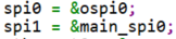
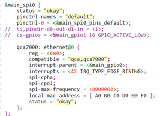
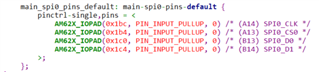
Output errors:

root@am62xx-evm:~# dmesg | grep spi1

[    1.526928] qcaspi spi1.0: ver=0.2.7-i, clkspeed=8000000, burst_len=5000, pluggable=0

[    1.534950] qcaspi spi1.0: Invalid signature (0xFFFF)

[    1.540113] qcaspi: probe of spi1.0 failed with error -14

The identified problem is that EXP_SPI0_CLK is not generating the expected output during Linux boot.

Is our modification correct, or did we miss anything?

Do you have any suggestions? Looking forward to your reply. Thank you.

  • The identified problem is that EXP_SPI0_CLK is not generating the expected output during Linux boot.

    I'm glad you looked at the signals to help debug this further.  Here's an E2E thread that has a working solution for AM62x SPI0. Can you please check it and see if you can make it work. Perhaps something with the pinmux or the address-cells / size-cells device properties is missing or wrong. https://e2e.ti.com/support/processors-group/processors/f/processors-forum/1263441/sk-am62-no-spi-signals-on-expansion-headers/4783737  Please report back any findings.

    Regards, Andreas

  • Sorry for the late reply. We've tried the methods mentioned above, but it still doesn't work.

    Then, we saw this related thread here: https://e2e.ti.com/support/processors-group/processors/f/processors-forum/1280645/sk-am64b-spi1-not-working?tisearch=e2e-sitesearch&keymatch=QCA# 

    We have modified the k3-am625-sk.dts file as follows:

    // SPDX-License-Identifier: GPL-2.0
    /*
     * AM625 SK: https://www.ti.com/lit/zip/sprr448
     *
     * Copyright (C) 2021-2022 Texas Instruments Incorporated - https://www.ti.com/
     */
    
    /dts-v1/;
    
    #include "k3-am62x-sk-common.dtsi"
    
    / {
    	compatible = "ti,am625-sk", "ti,am625";
    //	model = "Texas Instruments AM625 SK";
    	model = "TI AM625 SK PLC Test v0.07";
    
    
    	opp-table {
    		/* Add 1.4GHz OPP for am625-sk board. Requires VDD_CORE to be at 0.85V */
    		opp-1400000000 {
    			opp-hz = /bits/ 64 <1400000000>;
    			opp-supported-hw = <0x01 0x0004>;
    			clock-latency-ns = <6000000>;
    		};
    	};
    
    	memory@80000000 {
    		device_type = "memory";
    		/* 2G RAM */
    		reg = <0x00000000 0x80000000 0x00000000 0x80000000>;
    
    	};
    
    	vmain_pd: regulator-0 {
    		/* TPS65988 PD CONTROLLER OUTPUT */
    		compatible = "regulator-fixed";
    		regulator-name = "vmain_pd";
    		regulator-min-microvolt = <5000000>;
    		regulator-max-microvolt = <5000000>;
    		regulator-always-on;
    		regulator-boot-on;
    	};
    
    	vcc_5v0: regulator-1 {
    		/* Output of LM34936 */
    		compatible = "regulator-fixed";
    		regulator-name = "vcc_5v0";
    		regulator-min-microvolt = <5000000>;
    		regulator-max-microvolt = <5000000>;
    		vin-supply = <&vmain_pd>;
    		regulator-always-on;
    		regulator-boot-on;
    	};
    
    	vcc_3v3_sys: regulator-2 {
    		/* output of LM61460-Q1 */
    		compatible = "regulator-fixed";
    		regulator-name = "vcc_3v3_sys";
    		regulator-min-microvolt = <3300000>;
    		regulator-max-microvolt = <3300000>;
    		vin-supply = <&vmain_pd>;
    		regulator-always-on;
    		regulator-boot-on;
    	};
    
    	vdd_mmc1: regulator-3 {
    		/* TPS22918DBVR */
    		compatible = "regulator-fixed";
    		regulator-name = "vdd_mmc1";
    		regulator-min-microvolt = <3300000>;
    		regulator-max-microvolt = <3300000>;
    		regulator-boot-on;
    		enable-active-high;
    		vin-supply = <&vcc_3v3_sys>;
    		gpio = <&exp1 3 GPIO_ACTIVE_HIGH>;
    	};
    
    	vdd_sd_dv: regulator-4 {
    		/* Output of TLV71033 */
    		compatible = "regulator-gpio";
    		regulator-name = "tlv71033";
    		pinctrl-names = "default";
    		pinctrl-0 = <&vdd_sd_dv_pins_default>;
    		regulator-min-microvolt = <1800000>;
    		regulator-max-microvolt = <3300000>;
    		regulator-boot-on;
    		vin-supply = <&vcc_5v0>;
    		gpios = <&main_gpio0 31 GPIO_ACTIVE_HIGH>;
    		states = <1800000 0x0>,
    			 <3300000 0x1>;
    	};
    
    	vcc_1v8: regulator-5 {
    		/* output of TPS6282518DMQ */
    		compatible = "regulator-fixed";
    		regulator-name = "vcc_1v8";
    		regulator-min-microvolt = <1800000>;
    		regulator-max-microvolt = <1800000>;
    		vin-supply = <&vcc_3v3_sys>;
    		regulator-always-on;
    		regulator-boot-on;
    	};
    
    	wlan_lten: regulator-6 {
    		compatible = "regulator-fixed";
    		regulator-name = "wlan_lten";
    		regulator-min-microvolt = <3300000>;
    		regulator-max-microvolt = <3300000>;
    		vin-supply = <&vcc_3v3_sys>;
    		gpios = <&exp1 11 GPIO_ACTIVE_LOW>;
    	};
    
    	wlan_en: regulator-7 {
    		compatible = "regulator-fixed";
    		regulator-name = "wlan_en";
    		regulator-min-microvolt = <1800000>;
    		regulator-max-microvolt = <1800000>;
    		vin-supply = <&wlan_lten>;
    		enable-active-high;
    		gpios = <&main_gpio0 71 GPIO_ACTIVE_HIGH>;
    		pinctrl-names = "default";
    		pinctrl-0 = <&wlan_en_pins_default>;
    	};
    
    	vdd_core: regulator-8 {
    		/* output of TPS62826DMQ */
    		compatible = "regulator-fixed";
    		regulator-name = "vdd_core";
    		regulator-min-microvolt = <850000>;
    		regulator-max-microvolt = <850000>;
    		vin-supply = <&vcc_3v3_sys>;
    		regulator-always-on;
    		regulator-boot-on;
    	};
    };
    
    &main_pmx0 {
    	main_rgmii2_pins_default: main-rgmii2-pins-default {
    		pinctrl-single,pins = <
    			AM62X_IOPAD(0x184, PIN_INPUT, 0) /* (AE23) RGMII2_RD0 */
    			AM62X_IOPAD(0x188, PIN_INPUT, 0) /* (AB20) RGMII2_RD1 */
    			AM62X_IOPAD(0x18c, PIN_INPUT, 0) /* (AC21) RGMII2_RD2 */
    			AM62X_IOPAD(0x190, PIN_INPUT, 0) /* (AE22) RGMII2_RD3 */
    			AM62X_IOPAD(0x180, PIN_INPUT, 0) /* (AD23) RGMII2_RXC */
    			AM62X_IOPAD(0x17c, PIN_INPUT, 0) /* (AD22) RGMII2_RX_CTL */
    			AM62X_IOPAD(0x16c, PIN_OUTPUT, 0) /* (Y18) RGMII2_TD0 */
    			AM62X_IOPAD(0x170, PIN_OUTPUT, 0) /* (AA18) RGMII2_TD1 */
    			AM62X_IOPAD(0x174, PIN_OUTPUT, 0) /* (AD21) RGMII2_TD2 */
    			AM62X_IOPAD(0x178, PIN_OUTPUT, 0) /* (AC20) RGMII2_TD3 */
    			AM62X_IOPAD(0x168, PIN_OUTPUT, 0) /* (AE21) RGMII2_TXC */
    			AM62X_IOPAD(0x164, PIN_OUTPUT, 0) /* (AA19) RGMII2_TX_CTL */
    		>;
    	};
    
    	ospi0_pins_default: ospi0-pins-default {
    		pinctrl-single,pins = <
    			AM62X_IOPAD(0x000, PIN_OUTPUT, 0) /* (H24) OSPI0_CLK */
    			AM62X_IOPAD(0x02c, PIN_OUTPUT, 0) /* (F23) OSPI0_CSn0 */
    			AM62X_IOPAD(0x00c, PIN_INPUT, 0) /* (E25) OSPI0_D0 */
    			AM62X_IOPAD(0x010, PIN_INPUT, 0) /* (G24) OSPI0_D1 */
    			AM62X_IOPAD(0x014, PIN_INPUT, 0) /* (F25) OSPI0_D2 */
    			AM62X_IOPAD(0x018, PIN_INPUT, 0) /* (F24) OSPI0_D3 */
    			AM62X_IOPAD(0x01c, PIN_INPUT, 0) /* (J23) OSPI0_D4 */
    			AM62X_IOPAD(0x020, PIN_INPUT, 0) /* (J25) OSPI0_D5 */
    			AM62X_IOPAD(0x024, PIN_INPUT, 0) /* (H25) OSPI0_D6 */
    			AM62X_IOPAD(0x028, PIN_INPUT, 0) /* (J22) OSPI0_D7 */
    			AM62X_IOPAD(0x008, PIN_INPUT, 0) /* (J24) OSPI0_DQS */
    		>;
    	};
    
    	vdd_sd_dv_pins_default: vdd-sd-dv-pins-default {
    		pinctrl-single,pins = <
    			AM62X_IOPAD(0x07c, PIN_OUTPUT, 7) /* (P25) GPMC0_CLK.GPIO0_31 */
    		>;
    	};
    
    	main_gpio1_ioexp_intr_pins_default: main-gpio1-ioexp-intr-pins-default {
    		pinctrl-single,pins = <
    			AM62X_IOPAD(0x01d4, PIN_INPUT, 7) /* (B15) UART0_RTSn.GPIO1_23 */
    		>;
    	};
    
    	wlan_en_pins_default: wlan-en-pins-default {
    		pinctrl-single,pins = <
    				AM62X_IOPAD(0x124, PIN_OUTPUT, 7) /* (A23) MMC2_SDCD.GPIO0_71 */
    		>;
    	};
    
    	main_mmc2_pins_default: main-mmc2-pins-default {
    		pinctrl-single,pins = <
    			AM62X_IOPAD(0x120, PIN_INPUT, 0) /* (C24) MMC2_CMD */
    			AM62X_IOPAD(0x118, PIN_INPUT, 0) /* (D25) MMC2_CLK */
    			AM62X_IOPAD(0x114, PIN_INPUT, 0) /* (B24) MMC2_DAT0 */
    			AM62X_IOPAD(0x110, PIN_INPUT, 0) /* (C25) MMC2_DAT1 */
    			AM62X_IOPAD(0x10c, PIN_INPUT, 0) /* (E23) MMC2_DAT2 */
    			AM62X_IOPAD(0x108, PIN_INPUT, 0) /* (D24) MMC2_DAT3 */
    			AM62X_IOPAD(0x11c, PIN_INPUT, 0) /* (#N/A) MMC2_CLKB */
    		>;
    	};
    
    	main_wlirq_pins_default: main-wlirq-pins-default {
    		pinctrl-single,pins = <
    			AM62X_IOPAD(0x128, PIN_INPUT, 7) /* (B23) MMC2_SDWP.GPIO0_72 */
    		>;
    	};
    
    	main_spi0_pins_default: main-spi0-pins-default {
    		pinctrl-single,pins = <
    			AM62X_IOPAD(0x1bc, PIN_OUTPUT_PULLUP, 0) /* (A14) SPI0_CLK */
    			AM62X_IOPAD(0x1b4, PIN_OUTPUT_PULLUP, 0) /* (A13) SPI0_CS0 */
    			AM62X_IOPAD(0x1c0, PIN_OUTPUT_PULLUP, 0) /* (B13) SPI0_D0 */
    			AM62X_IOPAD(0x1c4, PIN_INPUT_PULLUP, 0) /* (B14) SPI0_D1 */
    			AM62X_IOPAD(0x009c, PIN_INPUT, 7) /* (V25) GPMC0_WAIT1.GPIO0_38 */
    		>;
    	};
    };
    
    &main_i2c1 {
    	exp1: gpio@22 {
    		compatible = "ti,tca6424";
    		reg = <0x22>;
    		gpio-controller;
    		#gpio-cells = <2>;
    		gpio-line-names = "GPIO_CPSW2_RST", "GPIO_CPSW1_RST",
    				   "PRU_DETECT", "MMC1_SD_EN",
    				   "VPP_LDO_EN", "EXP_PS_3V3_En",
    				   "EXP_PS_5V0_En", "EXP_HAT_DETECT",
    				   "GPIO_AUD_RSTn", "GPIO_eMMC_RSTn",
    				   "UART1_FET_BUF_EN", "WL_LT_EN",
    				   "GPIO_HDMI_RSTn", "CSI_GPIO1",
    				   "CSI_GPIO2", "PRU_3V3_EN",
    				   "HDMI_INTn", "PD_I2C_IRQ",
    				   "MCASP1_FET_EN", "MCASP1_BUF_BT_EN",
    				   "MCASP1_FET_SEL", "UART1_FET_SEL",
    				   "TSINT#", "IO_EXP_TEST_LED";
    
    		interrupt-parent = <&main_gpio1>;
    		interrupts = <23 IRQ_TYPE_EDGE_FALLING>;
    		interrupt-controller;
    		#interrupt-cells = <2>;
    
    		pinctrl-names = "default";
    		pinctrl-0 = <&main_gpio1_ioexp_intr_pins_default>;
    	};
    };
    
    &sdhci1 {
    	vmmc-supply = <&vdd_mmc1>;
    	vqmmc-supply = <&vdd_sd_dv>;
    };
    
    &sdhci2 {
    	status = "okay";
    	vmmc-supply = <&wlan_en>;
    	pinctrl-names = "default";
    	pinctrl-0 = <&main_mmc2_pins_default>;
    	bus-width = <4>;
    	non-removable;
    	ti,fails-without-test-cd;
    	cap-power-off-card;
    	keep-power-in-suspend;
    	ti,driver-strength-ohm = <50>;
    	assigned-clocks = <&k3_clks 157 158>;
    	assigned-clock-parents = <&k3_clks 157 160>;
    
    	#address-cells = <1>;
    	#size-cells = <0>;
    	wlcore: wlcore@2 {
    		compatible = "ti,wl1837";
    		reg = <2>;
    		pinctrl-names = "default";
    		pinctrl-0 = <&main_wlirq_pins_default>;
    		interrupt-parent = <&main_gpio0>;
    		interrupts = <72 IRQ_TYPE_EDGE_RISING>;
    	};
    };
    
    &cpsw3g {
    	pinctrl-names = "default";
    	pinctrl-0 = <&main_rgmii1_pins_default
    		     &main_rgmii2_pins_default>;
    
    	cpts@3d000 {
    		/* MAP HW3_TS_PUSH to GENF1 */
    		ti,pps = <2 1>;
    	};
    };
    
    &cpsw_port2 {
    	phy-mode = "rgmii-rxid";
    	phy-handle = <&cpsw3g_phy1>;
    };
    
    &cpsw3g_mdio {
    	cpsw3g_phy1: ethernet-phy@1 {
    		reg = <1>;
    		ti,rx-internal-delay = <DP83867_RGMIIDCTL_2_00_NS>;
    		ti,fifo-depth = <DP83867_PHYCR_FIFO_DEPTH_4_B_NIB>;
    		ti,min-output-impedance;
    	};
    };
    
    &mailbox0_cluster0 {
    	mbox_m4_0: mbox-m4-0 {
    		ti,mbox-rx = <0 0 0>;
    		ti,mbox-tx = <1 0 0>;
    	};
    };
    
    &ospi0 {
    	status = "okay";
    	pinctrl-names = "default";
    	pinctrl-0 = <&ospi0_pins_default>;
    
    	flash@0{
    		compatible = "jedec,spi-nor";
    		reg = <0x0>;
    		spi-tx-bus-width = <8>;
    		spi-rx-bus-width = <8>;
    		spi-max-frequency = <25000000>;
    		cdns,tshsl-ns = <60>;
    		cdns,tsd2d-ns = <60>;
    		cdns,tchsh-ns = <60>;
    		cdns,tslch-ns = <60>;
    		cdns,read-delay = <4>;
    
    		partitions {
    			compatible = "fixed-partitions";
    			#address-cells = <1>;
    			#size-cells = <1>;
    
    			partition@0 {
    				label = "ospi.tiboot3";
    				reg = <0x0 0x80000>;
    			};
    
    			partition@80000 {
    				label = "ospi.tispl";
    				reg = <0x80000 0x200000>;
    			};
    
    			partition@280000 {
    				label = "ospi.u-boot";
    				reg = <0x280000 0x400000>;
    			};
    
    			partition@680000 {
    				label = "ospi.env";
    				reg = <0x680000 0x40000>;
    			};
    
    			partition@6c0000 {
    				label = "ospi.env.backup";
    				reg = <0x6c0000 0x40000>;
    			};
    
    			partition@800000 {
    				label = "ospi.rootfs";
    				reg = <0x800000 0x37c0000>;
    			};
    
    			partition@3fc0000 {
    				label = "ospi.phypattern";
    				reg = <0x3fc0000 0x40000>;
    			};
    		};
    	};
    };
    
    &tlv320aic3106 {
    	DVDD-supply = <&vcc_1v8>;
    };
    
    #define K3_TS_OFFSET(pa, val)	(0x4+(pa)*4) (0x10000 | val)
    
    &timesync_router {
    	status = "okay";
    	pinctrl-names = "default";
    	pinctrl-0 = <&cpsw_cpts>;
    
    	/* Use Time Sync Router to map GENF1 input to HW3_TS_PUSH output */
    	cpsw_cpts: cpsw-cpts {
    		pinctrl-single,pins = <
    			/* pps [cpsw cpts genf1] in17 -> out12 [cpsw cpts hw3_push] */
    			K3_TS_OFFSET(12, 17)
    			>;
    	};
    };
    
    &main_spi0 {
    	status = "okay";
    	pinctrl-names = "default";
    	pinctrl-0 = <&main_spi0_pins_default>;
    	ti,pindir-d0-out-d1-in;
    //	cs-gpios = <&main_gpio1 16 GPIO_ACTIVE_LOW>;
    
    	qca7000: ethernet@0 {
    		compatible = "qca,qca7000";
    		reg = <0x0>;
    		interrupt-parent = <&main_gpio0>;
    		interrupts = <38 IRQ_TYPE_EDGE_RISING>;
    		spi-cpha;
    		spi-cpol;
    		spi-max-frequency = <8000000>;
    		local-mac-address = [ A0 B0 C0 D0 E0 F0 ];
    	};
    };


    But it also doesn't work.

    root@am62xx-evm:~# dmesg | grep spi1

    [ 5.381390] qcaspi spi1.0: ver=0.2.7-i, clkspeed=8000000, burst_len=5000, pluggable=0
    [ 5.396109] qcaspi spi1.0: Invalid signature (0x0000)
    [ 5.411051] qcaspi: probe of spi1.0 failed with error -14

    Is the spi interrupt configuration correct? Since we have configured (V25) GPMC0_WAIT1.GPIO0_38, GPIO-458 should appear, right?

    root@am62xx-evm:~# cat /sys/kernel/debug/gpio
    gpiochip2: GPIOs 344-367, parent: i2c/1-0022, 1-0022, can sleep:
    gpio-344 (GPIO_CPSW2_RST )
    gpio-345 (GPIO_CPSW1_RST )
    gpio-346 (PRU_DETECT )
    gpio-347 (MMC1_SD_EN |regulator-3 ) out hi
    gpio-348 (VPP_LDO_EN )
    gpio-349 (EXP_PS_3V3_En )
    gpio-350 (EXP_PS_5V0_En )
    gpio-351 (EXP_HAT_DETECT )
    gpio-352 (GPIO_AUD_RSTn )
    gpio-353 (GPIO_eMMC_RSTn )
    gpio-354 (UART1_FET_BUF_EN )
    gpio-355 (WL_LT_EN |regulator-6 ) out hi ACTIVE LOW
    gpio-356 (GPIO_HDMI_RSTn )
    gpio-357 (CSI_GPIO1 )
    gpio-358 (CSI_GPIO2 )
    gpio-359 (PRU_3V3_EN )
    gpio-360 (HDMI_INTn )
    gpio-361 (PD_I2C_IRQ )
    gpio-362 (MCASP1_FET_EN )
    gpio-363 (MCASP1_BUF_BT_EN )
    gpio-364 (MCASP1_FET_SEL )
    gpio-365 (UART1_FET_SEL )
    gpio-366 (TSINT# )
    gpio-367 (IO_EXP_TEST_LED )

    gpiochip1: GPIOs 368-419, parent: platform/601000.gpio, 601000.gpio:
    gpio-417 ( |am62-sk:green:heartb) out lo

    gpiochip0: GPIOs 420-511, parent: platform/600000.gpio, 600000.gpio:
    gpio-451 ( |tlv71033 ) out lo
    gpio-491 ( |regulator-7 ) out lo

    Regards, 

    Leo

  • Sorry for the late reply. We've tried the methods mentioned above, but it still doesn't work.

    The thread I pointed to https://e2e.ti.com/support/processors-group/processors/f/processors-forum/1263441/sk-am62-no-spi-signals-on-expansion-headers/4784647#4784647 has a know-good working example. Are you saying you followed all steps exactly, and don't see any signals on the SPI bus when trying to use the spidev_test utility?

    Regards, Andreas

  • Thank you for your reply. We have tested the light bar, it can light up. We can also observe the clock signal. The changes are as follows.

    &main_pmx0 {
        ...
        spi1_pins_default: spi1-pins-default {
            pinctrl-single,pins = <
                AM62X_IOPAD(0x01bc, PIN_INPUT, 0) /* (A14) SPI0_CLK */
                AM62X_IOPAD(0x01b4, PIN_INPUT, 0) /* (A13) SPI0_CS0 */
                AM62X_IOPAD(0x01c0, PIN_INPUT, 0) /* (B13) SPI0_D0 */
                AM62X_IOPAD(0x01c4, PIN_INPUT, 0) /* (B14) SPI0_D1 */
            >;
        };
        ...
    };
    
    &main_spi0 {
        status = "okay";
        pinctrl-names = "default";
        pinctrl-0 = <&spi1_pins_default>;
        ti,pindir-d0-out-d1-in;
        spidev@0 {
            spi-max-frequency = <6250000>;  /* 6.25 MHz */
            reg = <0>;
            compatible = "rohm,dh2228fv";
        };
    };

    Later, when we tried to use the same pin to connect the QCA7005, following the modifications as mentioned above, it failed. We don't see the clock signal. The obvious differences are that 'spidev@0' has changed to 'qca7000: ethernet@0', and there are changes in the contents inside.

    Regards, 

    Leo

  • Later, when we tried to use the same pin to connect the QCA7005, following the modifications as mentioned above, it failed. We don't see the clock signal. The obvious differences are that 'spidev@0' has changed to 'qca7000: ethernet@0', and there are changes in the contents inside.

    So your status is still exactly the below?

    root@am62xx-evm:~# dmesg | grep spi1

    [    1.526928] qcaspi spi1.0: ver=0.2.7-i, clkspeed=8000000, burst_len=5000, pluggable=0

    [    1.534950] qcaspi spi1.0: Invalid signature (0xFFFF)

    [    1.540113] qcaspi: probe of spi1.0 failed with error -14

    Did you use a logic analyzer to monitor the clock signal during boot?

    It looks like the driver is trying to probe the device, and reading back 0xFFFF which often means the SPI signals are not driven/configured correctly. But since you had a clock come out before when experimenting with the spidev device, at a minimum I'd also expect to see a clock here. Try step by step making your device SPI node look more and more like the working device node that you have, and see what specific difference gets you to a working clock signal.

    Regards, Andreas

  • So your status is still exactly the below?

    No, we currently see the following error messages.

    root@am62xx-evm:~# dmesg | grep spi1

    [ 5.381390] qcaspi spi1.0: ver=0.2.7-i, clkspeed=8000000, burst_len=5000, pluggable=0
    [ 5.396109] qcaspi spi1.0: Invalid signature (0x0000)
    [ 5.411051] qcaspi: probe of spi1.0 failed with error -14

    Did you use a logic analyzer to monitor the clock signal during boot?

    Yes, we don't see the clock signal.

  • [ 5.396109] qcaspi spi1.0: Invalid signature (0x0000)

    Interesting, something changed. Before you had the error of "qcaspi spi1.0: Invalid signature (0xFFFF)". But now the driver is reading 0x0000.

    Can you pin down/investigate what configuration (or setup?) change triggered this change?

    Regards, Andreas

  • Thank you for your help, it can work now.

    However, we still cannot determine what the problem is. Originally, the QCA7005 was on another board, and we connected it using wires to the SK-AM62B-P1. Now, with our custom board where the QCA7005 is on the board, we have succeeded.

    Thank you once again for your assistance.

    Best regards, 

    Leo

  • Hi Leo,

    Now, with our custom board where the QCA7005 is on the board, we have succeeded.

    I don't understand. Earlier you said you see no clock signal, but now you are saying you succeeded? So this can be closed? If so, can you please share your final device tree changes for reference?

    Thanks, Andreas

  • Yes, this issue can be closed. Below is the final device tree we changed, provided for reference. Thanks.

    &main_spi2 {
    	status = "okay";
    	pinctrl-names = "default";
    	pinctrl-0 = <&main_spi2_pins_default>;
    //	ti,pindir-d0-out-d1-in;
    
    	qca7000: ethernet@0 {
    		reg = <0>;
    		compatible = "qca,qca7000";
    		pinctrl-names = "default";
    		pinctrl-0 = <&main_qcairq_pins_default>;
    		interrupt-parent = <&main_gpio1>;
    		interrupts = <10 IRQ_TYPE_EDGE_RISING>;
    		spi-cpha;
    		spi-cpol;
    		spi-max-frequency = <8000000>;
    		local-mac-address = [ A0 B0 C0 D0 E0 F0 ];
    		status = "okay";
    	};
    };

    Best regards, 

    Leo