On the TDA4VM EVM, GPIO0_0 is connected to SW10. See TDA4VM EVM User Guide for SW10 location.
Can SW10 + GPIO0_0 be used to generate an interrupt on TDA4VM A72, with QNX running?
This thread has been locked.
If you have a related question, please click the "Ask a related question" button in the top right corner. The newly created question will be automatically linked to this question.
On the TDA4VM EVM, GPIO0_0 is connected to SW10. See TDA4VM EVM User Guide for SW10 location.
Can SW10 + GPIO0_0 be used to generate an interrupt on TDA4VM A72, with QNX running?
Yes, GPIO0_0 can be driven by SW10 to generate an interrupt to the A72 on the TDA4VM. Below patch and steps modify the GPIO example code in the PSDK QNX release, to allow push button, SW10 on the EVM, to be create an interrupt which is then handled by QNX on the A72.
This patch has been tested on the PSDK QNX 9.1 release
Using the TDA4VM EVM
Below steps assume that user has installed and built the PSDK QNX 9.1 release, and has a functional SD card already created. The steps are all covered in the SDK QNX link above.
Patch Install Steps:
Create environment variable PSDKQA_PATH, to be that of the psdkqa directory in your installation
Download patch:
Install patch
Copy over some additional header files from the SDK RTOS PDK Installation
Build Updated gpio binary
Copy gpio binary to SD card:
For help/usage of gpio example code, type below on target:
To test SW10
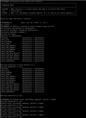
Expected Output

Why is Interrupt 392 specified?
GPIO interrupt routing / mapping information is available in the TDA4VM TRM.
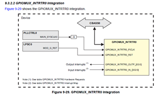
GPIO0 to GPIMUX_INTRTR0
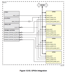
Below TRM screenshot indicates that there is a bank level interrupt for GPIO_0, that is going to GPIO_MUX_INTRTR0 (see block diagram). Any GPIO interrupt on GPIO0 would trigger this bank level interrupt. It is up to the interrupt handler to differentiate the particular interrupts from the GPIO bank and deal with the status bits accordingly.

The accompanying TRM table give the particular input port on the GPIO_MUX_INTRTR0 , GPIO0_INTR0_IN_256 (see table).

GPIOMUX_INTR0
The input port to the GPIOMUX_INTRTR0 for GPIO0_0 is known from previous section to be 256. This GPIO_INTRTRO_INP, instance must be programmed to an output port GPIOMUX_INTRTR0_OUTP. This will create a path across the mux from input port to output port.

Looking specifically how this interrupt could be routed to the A72 GIC, reference the table below, which shows that GPIO_MUX_INTR0_OUTP[63:8] can be mapped to GIC[447:392]. This table represents the available H/W mapping that the device has. The TRM table does not account for any S/W resource management that may be occurring.

Summary
The path through the TDA4VM device that an interrupt on GPIO Bank 0 would take to signal an interrupt on GIC instance 392 is: