This thread has been locked.

If you have a related question, please click the "Ask a related question" button in the top right corner. The newly created question will be automatically linked to this question.

AM6442: Profinet IEP Signals use case and hardware connection.

Part Number: AM6442
Other Parts Discussed in Thread: AM6421

Hello Team,

  • As per Profinet document, There is no need for specialized cables or connectors in a PROFINET network. Even if you are using IRT, the communication medium is standard Ethernet. Therefore, you can employ standard Ethernet cables and connectors.
  • We gained some insight from the following E2E link, but it's not comprehensive.

                  https://e2e.ti.com/support/processors-group/processors/f/processors-forum/1288523/am6421-am6421-and-iep-signals

                  PRG1_IEP0_EDC_SYNC_OUT0, (W7) - Required for PTCP/IRT

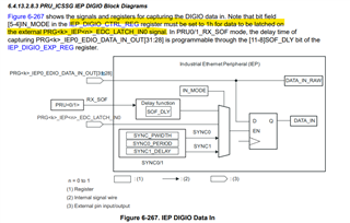
                  PRG1_IEP0_EDC_LATCH_IN0,  (V7) - Required if Customer needs to synchronise time from external source

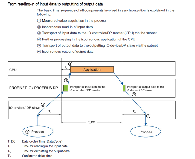
                  PRG1_IEP0_EDC_SYNC_OUT2, (U7) - Required if customer requires Isochronous mode

                  PRG1_IEP0_EDC_LATCH_IN1 (U13) - PRG1_IEP0_EDC_LATCH_IN1 (U13)

  • Are these signals used in special cases or specific to certain optional features of Profinet Class C-CC?
  • Are these signals are connected to outside world like PLC or other?

Thanks for your Support.

  • Hello Nikhil Jarande

    Thank you for the query.

    Please check if the below thread helps.

    (+) AMIC110: Support for ProfiNET IRT - Processors forum - Processors - TI E2E support forums

    SYNC0 is used for jitter measurement and SYNC1 is used for isochronous interrupt

    Please share your use case for me to further check.

    Regards,

    Sreenivasa

  • PRG1_IEP0_EDC_SYNC_OUT2

    The Isochronous Mode features supports two modes

    • GPIO mode - In this mode Signals will be generated on Sync1 pin at configured time.
    • Interrupt mode - In this mode, Hardware interrupt will be triggered at configured time Please note the signal will be generated in Interrupt mode also.

    What is Signal signifies?

         User can configure a maximum of two signals in a cycle. These signals can be used as Ti and To.

     What is Ti and To Signifies?

    PRG1_IEP0_EDC_SYNC_OUT0

    As per TI e2e forum It is used for jitter measurement and related to PTCP/IRT.

    What is PTCPT ?

    The shared clock is provided by an IEEE standard, known as IEEE 1588v2 (or IEEE 1588-2008).  This standard defines the Precision Time Protocol (PTP), and PROFINET extends PTP in a wrapper protocol called the Precision Transparent Clock Protocol (PTCP).  PTCP is used to not only share a common real-time clock across the network, but is also used to compute the delays inherent in both the network switches and the cabling between them.  IRT devices are capable of calculating those delays down to the nanosecond, and that accuracy is what allows all of the switches in the IRT network to enter and exit the IRT timeslice at exactly the same time. 

    Note -  Not much information in TI document. API I can see related to this PN_PTCP_configureSync0Pin(). Apart from that Sync0 and Sync1 signals shares common pulse width configuration.User need to take care of this while enabling ISOM features. By default Sync0 is configured to 25 micro seconds. Changing the ISOM signal pulse width will impact the Sync0 signal also

    PRG1_IEP0_EDC_LATCH_IN0,  (V7)

    Required if Customer needs to synchronise time from external source.

    PRG1_IEP0_EDC_LATCH_IN1 (U13)

    As per Ti e2e forum not used as of now.

    Note – Not able to find future road map. Datasheet it is mention as PRU_ICSSG Industrial Ethernet Distributed Clock Latch Input.

  • Thank you Sreenivasa for providing the e2e link. I've conducted some research and have included my findings in my previous comment for everyone's reference. Below is a summary, could you please take a moment to review it?

    PRG1_IEP0_EDC_SYNC_OUT2

    This signal can be used to generate interrupt to input peripheral or output peripheral. That will trigger process of reading input (Ti) or writing output (To).

    PRG1_IEP0_EDC_SYNC_OUT0

    This signal use to measure jitter. Is it relevant to compute the delays inherent in both the network switches and the cabling between them?  Use case is unknown.

    PRG1_IEP0_EDC_LATCH_IN0

    Required if Customer needs to synchronize time from external source. Most probably requirement for IRT. I'm not able find information. Any document , are you able to provide ?

  • Hello Nikhil Jarande

    Thank you.

    Help me understand the use case to be able to support or assign to the expert.

    Regards,

    Sreenivasa

  • Certainly, Sreenivas,

    We have successfully developed custom hardware for the Industrial Protocol utilizing Am6421. Presently, we are actively engaged in the implementation of the Ethernet/IP protocol. Additionally, in May, Profinet will become available from TI for both RT and IRT applications. We will be going with another hardware iteration, So it's imperative for us to gain a clear understanding of the purpose of EP signal lines in the TI EVM design respect to Profinet. Your continued support is greatly appreciated.

    Additional information , Product should support IRT with following option feature.

    1) Extended I&M: extended I&M shall be included.
    2) Shared Input: shall be included.
    3) Shared Device: shall be included.
    4) Name Assignment: name assignment via DCP, PDEV shall be included.
    5) Configuration in Run (CiR): CiR (also known as Dynamic Reconfiguration) shall be included.
    6) Time Sync: time sync shall be included, for time stamping data.
    7) Fast Start-up: shall be included. 
    8) Media Redundancy Protocol (MRP): MRP shall be included.
    9) System Redundancy: system redundancy shall be included, to enable S2 Redundancy.
    10) PROFINET IRT Isochronous Mode: isochronous mode shall be included. 
  • Hello Nikhil Jarande

    Thank you.

    I have assigned the thread to the expert to support.

    Regards,

    Sreenivasa

  • Hi Nikhil,

    PRG1_IEP0_EDC_SYNC_OUT2

    This signal can be used to generate interrupt to input peripheral or output peripheral. That will trigger process of reading input (Ti) or writing output (To).

    PRG1_IEP0_EDC_SYNC_OUT0

    This signal use to measure jitter. Is it relevant to compute the delays inherent in both the network switches and the cabling between them?  Use case is unknown.

    PRG1_IEP0_EDC_LATCH_IN0

    Required if Customer needs to synchronize time from external source. Most probably requirement for IRT. I'm not able find information. Any document , are you able to provide ?

    To clarify above points

    PRG1_IEP0_EDC_SYNC_OUT2
    The signal is used for Profinet IRT Isochronous mode. The signal / interrupt is generated at two configured time (Corresponding to Ti and To) within a cycle. This is to inform the application /stack about the time to consume a CPM and time to start copying the PPM 

    PRG1_IEP0_EDC_SYNC_OUT0
    This is used to generate periodic signals (once every cycle). The use case is to measure the jitter when you are running Profinet IRT which is with PTCP enabled

    PRG1_IEP0_EDC_LATCH_IN0
    Will get back to you on any document on this

    Please refer here for the Profinet features that will be supported - https://software-dl.ti.com/processor-industrial-sw/esd/ind_comms_sdk/am243x/09_01_00_03/docs/api_guide_am243x/INDUSTRIAL_COMMS_TI_STACK.html#INDUSTRIAL_COMMS_TI_STACK_PROFINET

    Let me know if you have more questions

    Regards,
    Prajith

  • Thank you for providing the information. However, it doesn't offer a clear understanding of the use case. Are these hardware lines restricted solely to internal product functions such as application, stack, jitter measurement, and synchronizing time from an external source? Or is there a need for them to connect to the outside world, such as with a PLC? This distinction is crucial for us as we are developing custom hardware with AM6421 and currently implementing Ethernet/IP protocol, with plans for Profinet IRT in the future. As we are in the process of hardware iteration, it's vital for us to have a clear understanding in advance of the use case and connectivity requirements in relation to the hardware. Thank you for your assistance in clarifying this matter.

  • Hi Prajith,

    Just gentle reminder for previous query. Thanks for your support.

    Regards,

    Nikhil

  • Hi Nikhil,

    I wont be able to comment on the product requirements here. We are providing hooks for the product to use the functionality.  You can let us know if you have any specific  requirements from you side, we can confirm if they can be supported or not

    Regards,
    Prajith

  • Hi Prajith,

    Let's simplify this.

    •  I have added table which shows example of hardware Line and related Profinet feature. Can you fill this table ?

      Hardware Line

      Profinet Feature

      PRG1_IEP0_EDC_SYNC_OUT2

      CC - Isochronous operation

      PRG1_IEP0_EDC_SYNC_OUT0


      PRG1_IEP0_EDC_LATCH_IN0


      PRG1_IEP0_EDC_LATCH_IN1


    • Can you answer following questions

      Is any hardware lines need to be connected PLC ? if yes specify hardware line.

                Is any hardware line need to be electronic component ? if yes specify hardware line.

  • Hi Prajith,

    Can you answer my previous comment ? Thanks for your support and expert advise.

    Regards,

    Nikhil Jarande

  • Hi Nikhil

    Is any hardware lines need to be connected PLC ? if yes specify hardware line.
    Not that i am aware of

    Is any hardware line need to be electronic component ? if yes specify hardware line
    Did not understand this question. Is your question about any reason to connect the line to any external devices? if yes there are use cases where you can connect Periodic pulse to an external FPGA or other devices for synchronization or sampling purposes

    Hardware Line

    Profinet Feature

    PRG1_IEP0_EDC_SYNC_OUT2

    CC - Isochronous operation - Triggered by firmware based on configuration

    PRG1_IEP0_EDC_SYNC_OUT0

    CC - Periodic pulse - Triggered by firmware in every cycle

    PRG1_IEP0_EDC_LATCH_IN0

    Depends on application - No dependency on firmware 

    PRG1_IEP0_EDC_LATCH_IN1

    Depends on application - No dependency on firmware 

    AM243 TRM section 6.4.13 has more details on how these latch pins can be used

    Hope this answer your question

    Regards,
    Prajith

  • Hi Prajith,

    This is useful information. Thanks for your support.

    PRG1_IEP0_EDC_LATCH_IN