A related question is a question created from another question. When the related question is created, it will be automatically linked to the original question.
If you have a related question, please click the "Ask a related question" button in the top right corner. The newly created question will be automatically linked to this question.
[FAQ] SK-AM62X/SK-AM62A-LP: Testing MCAN External Loopback example using external transceiver TCAN1042D
The AM62 SKs support CAN-FD, but do not carry a CAN-FD transceiver to experiment with. Hence, to test the full functionality of CAN, we need to connect an external transceiver. MCU+ SDK contains internal loopback example, in this guide, we will modify it, to make it compatible to run MCAN on an external setup.
To establish MCAN external loopback communication, the tested hardware setup includes a AM62A, connected to the TCAN, which is connected to a PCAN module, and the data can be viewed on PCAN view software.
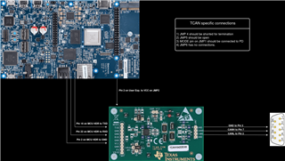
AM62x/AM62A EVM to TCAN connections:
MCU_MCAN0_TX --> TXD JMP 2 on TCAN
MCU_MCAN0_RX --> RXD JMP 2 on TCAN
VCC (5 V) --> VCC JMP2 on TCAN
GND --> GND JMP2 on TCAN
TCAN to PCAN connections:
CANL on TCAN JMP7 -->CANL on PCAN
CANH on TCAN JMP7 -->CANH on PCAN
GND on TCAN JMP7 -->GND on PCAN
Note:
TCAN1042D EVM requires 5V supply(min. 4.5V) to operate properly. Hence for this experiment, 5V pin supply pin on User Expansion is enabled from Linux terminal using the below steps:
//To find out the GPIO chipset name
# gpiodetect
.
.
gpiochip3 [1-0022] (24 lines)

//gpiochip3 has ID [1-0022] in which ‘1’ means I2C1 and ‘0022’ is I2C address
//gpiochip3 is the GPIO chipset of the IO Expander.
# gpioinfo gpiochip3
gpiochip3 - 24 lines:
    ...
    line   5: "EXP_PS_3V3_En" unused input active-high
    line   6: "EXP_PS_5V0_En" unused input active-high
    ...

//EXP_PS_5V0_EN is line 6. To turn on the 5V pins, run the following command:
# gpioset gpiochip3 6=1
Software setup:
Changes required in internal loopback example to run it as external loopback example This function App_mcanConfig() operates the example in internal or external loopback method, based on the parameter passed into it. App_mcanConfig(TRUE) -> Internal loopback App_mcanConfig(FALSE) -> External loopback
PCAN software setup Download and Install the PCAN-View from https://www.peak-system.com/PCAN-View.242.0.html?&L=1 Click on CAN in the menu bar and conncet to PCAN-Usb. Set Mode as ISO CAN FD and sampling point in Nominal Bit Rate as 85 percent and Sampling Point in Data Bit Rate as 87.5 percent. Rest as default. When data is recieved from MCAN instance, it will be visible as shown in the image below in PCAN-View.
Syscfg settings: For testing purposes MCU_MCAN0 instance is used, all harwdare and software connections are based on this particular instance. If any other instance is used, make sure to set it as MCAN instance via Sysconfig.
MCAN bit timing configuration settings:
Bitrates and sampling point are calculated using the following formulae:
bit rate(bits per second) = (CAN clock in Hz) / BRP / (1 + TSEG1 + TSEG2)
(Note: Values selected in Sysconfig / the values set in structure are directly programmed in MCAN register bit fields. The actual interpretation by the hardware of this value is such that one more than the value programmed.)
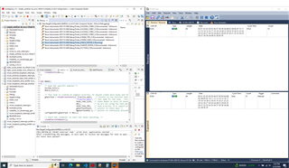
Make the hardware and software setups, re-build the internal loopback example with software changes. (examples\drivers\mcan\mcan_loopback_interrupt\am62ax-sk\mcu-r5fss0-0_freertos)
Connect the PCAN module, calculate the Sampling Points and data bit rates, and set it correctly in PCAN view.
Run the example, and the TX data will be visible on PCAN view Receive tab.
After successful reception of data, the data has to be transmitted ten times from PCAN-View for test to end.
Sample Output:
[MCAN] External read - write test, application started ...
After transmitting messages it will wait to recieve ten messages for test to pass ...
All tests have passed!!
Things to keep in mind while creating the setup:
1) CAN bus should have proper termination(120 ohm).
2) The CAN parameters including sampling point needs to be calculated and set correctly on the host side, matching configurations of the board (refer syscfg)
3) SoC pins/PADs for CAN are configured properly.
4) CAN module is powered up and configured properly.