


The .dat file output of the Pin Mux Utility for the DM816x doesn't match the selection in the gui.
For example:
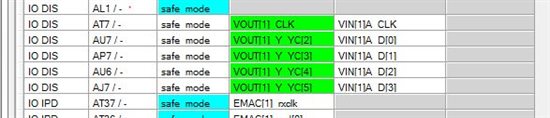
Translates to:
Pad 1 CYG AL1 - safe_mode 4 SafeMode Reserved Reserved Reserved 1 2
Pad 1 CYG AT7 - safe_mode 4 NotSelected Selected NotSelected Reserved 1 2
Pad 1 CYG AU7 - safe_mode 4 NotSelected Selected NotSelected Reserved 1 2
Pad 1 CYG AP7 - safe_mode 4 NotSelected Selected NotSelected Reserved 1 2
Pad 1 CYG AU6 - safe_mode 4 NotSelected Selected NotSelected Reserved 1 2
Pad 1 CYG AJ7 - safe_mode 4 NotSelected Selected NotSelected Reserved 1 2
Pad 1 CYG AT37 - safe_mode 4 SafeMode NotSelected Reserved Reserved 1 0
This is with version 1.1.5.0.
Is there a newer version?
Thanks,
Tim.

