This thread has been locked.

If you have a related question, please click the "Ask a related question" button in the top right corner. The newly created question will be automatically linked to this question.

DRA829V: Power down sequence

Part Number: DRA829V
Other Parts Discussed in Thread: DRA829

We are using the two recommended PMICs TPS65941213-Q1 and TPS65941111-Q1 running them according to pdn-0C. https://www.ti.com/lit/ug/slvuc99a/slvuc99a.pdf?ts=1709827472401

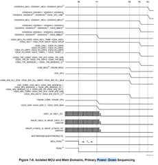
According to DRA829 datasheet power down should look like this:

And according to PDN-0C the PMIC should power down according to:

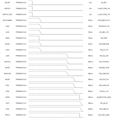
I measure the following:

D0 VSYS_MCUIO_3V3
D1 VSYS_IO_3V3
D2 VSYS_IO_1V8
D3 VDA_MCU_1V8
D4 VDA_PLL_1V8
D5 VDD_PHYIO_1V8
D6 VDD_MCU_0V85
D7 VDD_CPU_AVS
D8 VDA_DLL_0V8
D9 VDD_CORE_0V8
D10 VDD_CORE_RAM_0V85
D11 VDD_DDR_1V1
D12 PMIC_EN
D13 MCU_PORz

Most of the rails power down as intended. However VDA_DLL_0V8 (3.77ms), VDA_MCU_1V8 (4.03m) and VDA_PLL_1V8 (3.87ms) does not power down at the correct timestamp.

They all power down after VSYS_MCUIO_3V3 and VSYS_IO_3V3 which should be the last two powersupplys to ramp down.

The rails are connected from the PMICs according to PDN-0C.

We have a help processor pulling MCU_PORz low first, and then PMIC_EN low.

  • I agree that VDA_DLL_0V8 (PMIC-A, LDO3, Tdn2 = 2.5ms), VDA_PLL_1V8 (PMIC-B, LDO4, Tdn3 = 3ms) & VDA_MCU_1V8 (PMIC-A, LDO4Tdn3 = 3ms) are not aligned in the correct/desired power down time steps (Tdn2 & Tdn3).  Please double check the scope probe connections are correct for these power rails.

    I will add the TPS6594x-Q1 PMIC FAE (Michael Gambrill) and request him to pull test waveforms from both TPS65941213-Q1 (PMIC-A) and TPS65941111-Q1 (PMIC-B) to verify timing & NVM revision.

    In the meantime, could you also capture the following missing signals & power rails:
    SOC_PORz (PMIC-A, GPIO11),
    VDD_DDR_1V8 (PMIC-A, LDO1) 
    VDD_MCUIO_1V8 (PMIC-A, LDO2). 

    You may have just missed these or your end product may not be using these power rails.  Please confirm:
    1. Is your end product supporting DDR_Retention low power modes?
        (If yes, then VDD_DDR_1V8 needs to LPDDR4 VDD1.)
    2. Is your product design to support Isolated MCU & Main PDN scheme?
        (If yes, then VDDSHV1_MCU is typ connected to VDD_MCUIO_1V8 to support MCU Flash IO.  Your SCH snap-shot shows PMIC-A, LDO2 connected to "Vout_LDO2" net. How       is it being used?)

  • Hi Bill,

    Thanks for a quick reply! Please do add relevant persons to the issue.

    I have added the "missing" rails/reset to the measurement. D14 - SOC_PORz, D15 - VDD_DDR_1V8. VDD_MCUIO_1V8 is not used see explanation below.

    VDD_DDR_1V8 ramps down at correct timestamp ~3ms

    1. Yes we want to have that possibility.
    2. Right now we are not using the isolated MCU. We want to have that possibility for future updates to do so. LDO2 is not connected to anything. Our flash is running from 3v3 rail where MCU IO 3v3 and Main IO 3v3 are seperated with two different load switches.
    Load switches are controlled by GPIO 9 on PMIC A and GPIO11 on PMIC B.

    Br

    Anders

  • Thanks for capturing updated pwr down seq.

    SoC_PORz is disabled ~0.5ms correctly.

    VDD_DDR_1V8 is disabled ~3ms correctly.

    Understand your comment on VDD_MCUIO_1V8 is presently not used. However, please confirm you have installed external passive components (inductor, caps) to stabilize power resource & avoid internal PMIC errors per PMIC DS. Also be aware, the MCU Flash memory data rate will be restricted when using 3.3V IO signaling. The higher Flash data rates need 1.8V.

  • They are connected (see schematic above). Understood!

    Looking forward to more feedback! 

  • Hello Anders,

    Most of the rails power down as intended. However VDA_DLL_0V8 (3.77ms), VDA_MCU_1V8 (4.03m) and VDA_PLL_1V8 (3.87ms) does not power down at the correct timestamp.

    I don't think it is a coincidence at all 3 of this signals are powered by PMIC LDOs. The LDOs do not have a controlled active discharge like the BUCK s do. Therefore they turn off more slowly without a load much of a load present. The timestamps in the PMIC user guide represent the approximate point that the rail starts to turn off. Since you are using a logic analyzer, you can only see when the rail passes a voltage threshold, not when it starts to turn off. 

    See this capture from validation using analog measurement. LDO3 starts ramping down at ~ 2.5ms. 

  • Hi Michael,

    I have confirmed the same behavior for my board. Is there a problem that the LDOs discharge much slower than other rails? or is this behavior okay?

    //Anders

  • It is not a problem if the LDOs discharge slower than the BUCKs. However, they should drop below 150mV before a subsequent recovery or power up attempt. So there is such a thing as "too" slow. This is usually only a problem in the presence of too much output capacitance.