This thread has been locked.

If you have a related question, please click the "Ask a related question" button in the top right corner. The newly created question will be automatically linked to this question.

AM6442: Alignment of 1-PPS from AM64

Part Number: AM6442
Other Parts Discussed in Thread: LMK5B33216

Hi,

i'm running a PTP stack which shifts the main 25 MHz clock to AM64 to achieve ToD alignment.

I have three devices leader (L), follower 1 (F1), and follower 2 (F2).

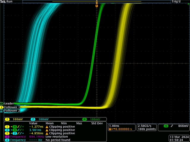
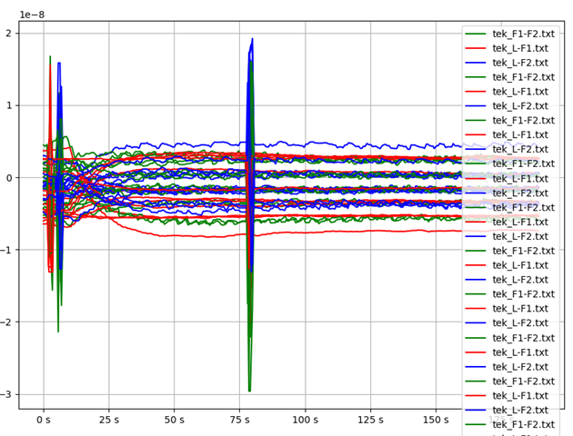
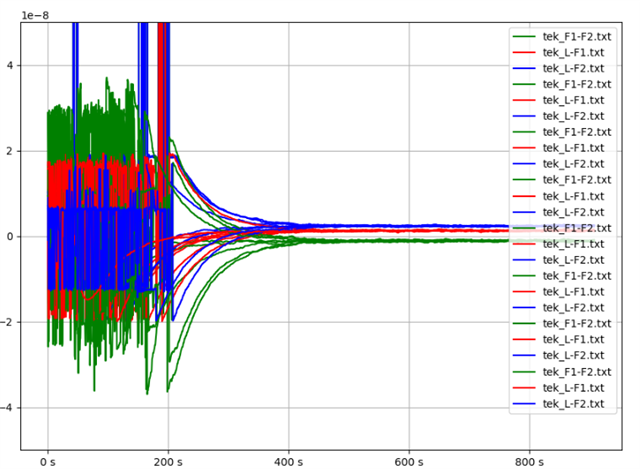
Below you can see a plot 1-PPS alignment from AM64 SK EVM from J3 with...

  • green as follower time vs follower 2.
  • red with leader vs. follower 1
  • and blue with leader vs. follower 2.

For several runs in which I rebooted the system and restarted my PTP stack.  The time error appears to be +5 ns to -10 ns on the alignment.

How can this be improved?

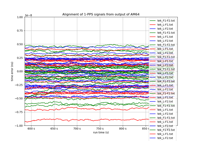
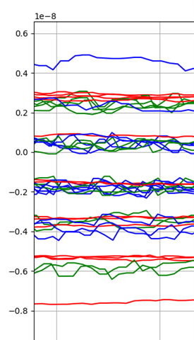
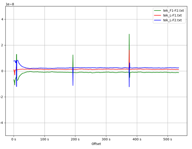
Here is a lessor set of data where I just start/stop my PTP stack.  In this case alignment occurs deterministically, although I would like it to be all closer to 0.

I also did I a test where I turned the 1-PPS off/on... I must do this once to get 1-PPS to properly reflect the TOD.  It seems there is no 'sample' error caused by this action.  So why the non-determinism in my first plot?

testptp -i /dev/ptp0 -P 0
testptp -i /dev/ptp0 -P 1

Note, since my PTP stack is doing DCO of LMK5B33216 externally, I do not believe the bug discussed below impacts me... perhaps I'm wrong.
https://e2e.ti.com/support/processors-group/processors/f/processors-forum/1256953/sk-am62-pps-out-not-acting-as-expected

Which I found from:
https://e2e.ti.com/support/processors-group/processors/f/processors-forum/1248172/sk-am62-high-precission-pps-input

73,
Timothy

  • Hi Timothy,

    Please expect a delay in response from me until next week as I'm attending all-day trainings this week. I will look into your inquiry once I'm back.

    -Daolin

  • Hi Timothy,

    This issue has been brought to my attention as an escalation so I'm going to try to look more into this during lunch and after my full day trainings this week. 

    For improving the delay/alignment numbers:

    Typically, when running the out of box ptp4l on Linux on AM64x device, the best accuracy in time that can be reached is on the level of single-digit nanoseconds. Even the output for ptpt4l for rms column is in units of nanoseconds.

    Due to this and the fact that the measurements for an output signal to reach a physical pin from the time sync router seems to be within 14ns (also on ns level). From https://e2e.ti.com/support/processors-group/processors/f/processors-forum/1061474/faq-am64x-what-is-the-time-sync-router-for-how-do-i-use-it?tisearch=e2e-sitesearch&keymatch=faq%3Atrue, which I think you've read.

    Some trivial improvements could be to decrease the cable length connection between each device or design the board traces such that the length is shorter to travel to the physical pin. 

    For accuracy of measurements/if deterministic or not:

    I did some research in ways for measuring slave clock accuracy and I see that there are several options to measure, including comparing 1PPS like you did. This resource (slide 8) also lists some shortcomings of 1PPS measurement including "implementation of 1PPS itself is sometimes imperfect, causing a phase offset or jitter" and "the devices under test have to be relatively close together". The other options of measurement (ingress method, egress method, reverse sync method) could be worth trying but they also have their own shortcomings.

    Another thing is that the 1PPS signal has to go through the time sync router, take time to go through board traces to reach the physical pin, which can add latencies. Because of this, I'm not sure if the 1PPS alignment measurements directly reflect what the output of ptp4l shows. 

    I hope some of my comments here are helpful, as I'm also trying to learn/ramp up about PTP. Please let me know if you have additional questions.

    -Daolin

  • Hi Daolin,

    So I am not running ptp4l, I'm using a custom high performance stack.  The setup has the AM64 and PHY receiving its 25 MHz clock from LMK5B33216.  The PTP stack DCOs the LMK5B33216 via SPI interface to adjust the clock frequency to speed up/slow down the AM64 clock so the ToD may align.  The LMK5B33216 supports a very fine DCO in ppt range.  With this setup we are able to get very good time alignment/variation in 100s of ps.

    All my LMK5B33216 are simulated to be using SyncE -- the input frequency to the LMK5B33216 is the same to all PTP nodes.  Incidentally on the Follower1 board the PHY & AM64 are DCOed.  on the Follower2 board the PHY frequency does not change, it is locked to the SyncE frequency and only the AM64 receives the DCOed 25 MHz.  Leader board doesn't do any DCO.  So PHY and AM64 are at the same constant "SyncE" frequency.

    However since the 25 MHz clock is used as feedback, and I want to ability to phase align clocks from LMK5B33216 between PTP nodes, I am using the 1-PPS output of the AM64 to lock another DPLL on the LMK5B33216 to.  Then I can do zero delay with another of my clocks to get deterministic phase.

    The problem is that the 1-PPS outputs are not aligned well... and it changes from boot to boot as illustrated by my first image above.  Below is the 1-PPS output from J3 for my leader, and two followers.  I've collected data with persistence on to show that the variation is actually sub-1ns of the 1-PPS output.  Further, my DPLL would filter and average out any variation... wander attenuation.  So at this time, I don't see a concern for latency variation of 1-PPS output.  The image below measures that variation and it's not impacting my performance.  It's the non-determinism at start-up that is the problem.

    I don't know why/where this uncertainty comes in.  Sometimes I boot up and start the stack and two of the 1-PPS outputs are aligned.

    73,
    Timothy

  • Hi Timothy,

    Just so I'm understanding correctly, each time upon boot-up, the 1-PPS output variation between the leader, follower1, and follower2 are different from the previous boot-up variations? For the sub-1ns variation result was that result from just after one instance of bootup and you're seeing for instance the next bootup, the variation could be +5 ns to -10 ns on the alignment (based on your first plot)?

    If that is the case, I currently don't know why there is this variation for every bootup. I'm thinking it may have something to do with the timing for PTP stack to be up. What is the alignment requirement for your application? Sub-1ns?

    -Daolin

  • Just so I'm understanding correctly, each time upon boot-up, the 1-PPS output variation between the leader, follower1, and follower2 are different from the previous boot-up variations? For the sub-1ns variation result was that result from just after one instance of bootup and you're seeing for instance the next bootup, the variation could be +5 ns to -10 ns on the alignment (based on your first plot)?

    Correct for same boot, starting stopping PTP stack results in same.

    Also starting stopping 1-PPS output using testptp resulted in the same phase... although I didn't have too many cycles.

    Here's a test I did today where I did an 'ifconfig eth0 down' 'ifconfig eth0 up' for each device.  The big blip when I turned 1-PPS off/on.

    Looks like these different phases are just under 2 ns apart.  Zoom of above.

    73,
    Timothy

  • Hi Timothy,

    Is the 1-PPS sourced from your custom PTP stack or from the Linux PTP stack? That is, is the testptp application you're using to run 1-PPS invoking the custom PTP stack or was it sourced from Linux Kernel tools under "selftests"? 

    If the latter, could you try running ptp4l and check if the resulting time variations from board to board still has variation from boot to boot? If it doesn't and it only appears to be the case that invoking 1-PPS shows variation from boot to boot, something might be inconsistent with the path from the CPTS to SYNC_OUT pin for 1-PPS between boots....

    -Daolin

  • Is the 1-PPS sourced from your custom PTP stack or from the Linux PTP stack? That is, is the testptp application you're using to run 1-PPS invoking the custom PTP stack or was it sourced from Linux Kernel tools under "selftests"? 

    The 1-PPS is sourced by using the testptp program to turn it on.  Note if I turn it on when I start my stack, I have to turn the 1-PPS off/on after the initial time sync from the PTP stack.  I turn off/on with...

    /usr/bin/kselftests/ptp/testptp -d /dev/ptp0 -P 0
    /usr/bin/kselftests/ptp/testptp -d /dev/ptp0 -P 1

    Note, I am using:
    PROCESSOR-SDK-LINUX-RT-AM64X
    Processor SDK RT-Linux for AM64x

    Version: 08.06.00.42
    Release date: 27 Feb 2023

    uname -a result:
    Linux follower2 5.10.168-rt83-gc1a1291911 #1 SMP PREEMPT_RT Mon Feb 27 14:03:20 UTC 2023 aarch64 aarch64 aarch64 GNU/Linux

    If the latter, could you try running ptp4l and check if the resulting time variations from board to board still has variation from boot to boot?

    Ok, I've started a test to check this.

    73,
    Timothy

  • Timothy,

    Thanks for clarifying

    Keep me updated with your findings

    -Daolin

  • Hi,

    My findings is that the 1-PPS output is does not continue to track and drifts off.  I need to start/re-start to keep PTP4L 1-PPS tracking.  I think this may relate to bug: https://e2e.ti.com/support/processors-group/processors/f/processors-forum/1256953/sk-am62-pps-out-not-acting-as-expected

    Otherwise, I don't think looking at PTP4L is the path to resolve this issue.

    For example just taking up/down ethernet port results in "quantized" phase error, a ~7steps of ~1.80 ns apart.  However the restart phase error is not 'quantized' and appears more random.

    73,
    Timothy

  • Hi Timothy,

    Apologies for the later response. I need some time to read over the thread you linked, and will respond tomorrow.

    -Daolin

  • Hi Timothy,

    I read over what is described in https://e2e.ti.com/support/processors-group/processors/f/processors-forum/1256953/sk-am62-pps-out-not-acting-as-expected and the corresponding Jira ticket filed for it (LCPD-36876). It seems to me that the customer's test sequence of first starting 1-PPS before trying to synchronize with ptp4l shows non-synchronized 1-PPS. Then running ptp4l after starting 1-PPS results in the 1-PPS not showing any effects of ptp4l synchronization until restarting the 1-PPS signal. 

    The ongoing discussion in LCPD-36876 seems to be discussing whether the 1-PPS should update based on real-time the synchronization of ptp4l or if 1-PPS only updates after you restart it following any changes to the ptp4l synchronization is the intended requirement of 1-PPS. One of the software developer's conclusions was "synchronizing the clocks first followed by enabling PPS signal provides intended functionality". 

    Your findings that ptp4l 1-PPS drifts after a while seems to be related to this discussion as you mentioned. Does this drift occur when you leave ptp4l running in the background or when you stop ptp4l after the 1-PPS is synchronized (after a period of time 1-PPS drifts)? How soon does 1-PPS start drifting? When you were collecting data on changes in synchronization from boot-to-boot, did you run ptp4l to obtain synchronization before starting 1-PPS?

    >>"Otherwise, I don't think looking at PTP4L is the path to resolve this issue."

    Since the 1-PPS you are using is closely coupled with ptp4l synchronization, I still think it's worth investigating any potential issues with ptp4l and see if they might affect the 1-PPS that gets generated. But I will check with Pekka if this is right direction to go for investigating the synchronization issues you are seeing.

    -Daolin

  • The time error appears to be +5 ns to -10 ns on the alignment.

    How can this be improved?

    I think this is roughly at the limit of 1Gbit/s RGMII based interface and IEEE1588, 125MHz clock and an asynchronous boundary (8ns). For example https://www.ieee802.org/1/files/public/docs2021/60802-Alsup-Timestamp-Precision-0321-v01.pdf  highlights this, and it lines up with what we see in AVNU TSN plugfests.