This thread has been locked.

If you have a related question, please click the "Ask a related question" button in the top right corner. The newly created question will be automatically linked to this question.

AM625: PRU - UART TX/RX error

Part Number: AM625

I'm trying to do a UART serial loopback through the AM625 PRU, however, it's not working as desired, even using the Texas examples. Basically, TX/RX doesn't work.

The version of Code Composer Studio is 12.6.0.00008

I'm using the firmware that comes directly from the Texas Intruments website: tisdk-default-image-am62xx-evm.wic. I didn't configure anything different in it, just using the default version.

Below is the code attached and a video of the unexpected situation. Thanks

The code is here:

#include <stdint.h>
#include <pru_uart.h>
#include "resource_table.h"

#define FIFO_SIZE   16
#define MAX_CHARS   8

#define TX_PR0_UART_PINMUX ( *( volatile uint32_t * )( 0x000F41DC ) )
#define RX_PR0_UART_PINMUX ( *( volatile uint32_t * )( 0x000F41D8 ) )

void main(void)
{
    uint8_t tx = 0;
    volatile uint8_t rx = 0;
    uint8_t cnt = 0;

    volatile uint32_t status_0 = 0;
    volatile uint32_t status_1 = 0;

    char* hostBuffer;

    volatile uint32_t map_0 = 0;
    volatile uint32_t map_1 = 0;

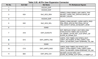
    // PINMUX configuration for UART_PRU TX/RX on 40 pins expansions header
    TX_PR0_UART_PINMUX &=~ 0b111;
    TX_PR0_UART_PINMUX |= 0b110;

    map_0  = TX_PR0_UART_PINMUX;

    RX_PR0_UART_PINMUX &=~ 0b111;
    RX_PR0_UART_PINMUX |= 0b110;

    map_1 = RX_PR0_UART_PINMUX;

    //  115200 baud rate - 16x oversample - 192MHz clk
    CT_UART.DIVLSB_bit.DLL = 104;
    CT_UART.DIVMSB_bit.DLH = 0b0;
    CT_UART.MODE_bit.OSM_SEL = 0b0;

    // INTERRUPTS:
    // Receiver Data Available Interrupt
    // Transmitter Holding Register Empty Interrupt
    // Line Status Interrupt
    CT_UART.INT_EN_bit.ERBI = 0b1;
    CT_UART.INT_EN_bit.ETBEI = 0b1;
    CT_UART.INT_EN_bit.ELSI = 0b1;

    // FIFO config
    CT_UART.INT_FIFO_bit.FCR_FIFOEN = 0b1;
    CT_UART.INT_FIFO_bit.FCR_RXCLR = 0b1;
    CT_UART.INT_FIFO_bit.FCR_TXCLR = 0b1;
    CT_UART.INT_FIFO_bit.FCR_DMAMODE1 = 0b1;

    // 8-bit word, 1 stop bit, no parity, no break control and no divisor latch
    CT_UART.LCTR_bit.WLS0 = 0b1;
    CT_UART.LCTR_bit.WLS1 = 0b1;

    // enable UART to act free and enable TX RX
    CT_UART.PWR_bit.FREE = 0b1;
    CT_UART.PWR_bit.URRST = 0b1;
    CT_UART.PWR_bit.UTRST = 0b1;

    // Enable LOOPBACK and disable AFE and RTS functionality
    CT_UART.MCTR_bit.LOOP = 0b0;
    CT_UART.MCTR_bit.AFE = 0b0;
    CT_UART.MCTR_bit.RTS = 0b0;

    hostBuffer = "abc";

    while(1)
    {
        cnt = 0;

        while(1)
        {
            //status verify
            status_0 = CT_UART.LSR1;
            status_1 = CT_UART.INT_FIFO;

            if ((tx = hostBuffer[cnt]) == '\0') break;

            cnt++;

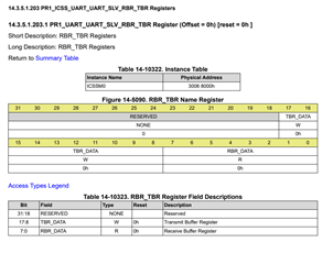
            CT_UART.RBR_TBR_bit.TBR_DATA = tx;

            //status verify
            status_0 = CT_UART.LSR1;
            status_1 = CT_UART.INT_FIFO;

            while ( CT_UART.LSR1_bit.DR );

            //status verify
            status_0 = CT_UART.LSR1;
            status_1 = CT_UART.INT_FIFO;

            rx = CT_UART.RBR_TBR_bit.RBR_DATA;

            //status verify
            status_0 = CT_UART.LSR1;
            status_1 = CT_UART.INT_FIFO;

            while ( !CT_UART.LSR1_bit.TEMT );
        }
    }
        // Disable UART before halting
        CT_UART.PWR_bit.FREE = 0b0;
        CT_UART.PWR_bit.URRST = 0b0;
        CT_UART.PWR_bit.UTRST = 0b0;

        // halt PRU core
        __halt();
}

The video of the issue is here:

  • Hello Rafael,

    Can you please also attach the linker.cmd file and resource table file you are using?

    Just to remind me, what version of PRU SW Support Package (PSSP) are you using?

    Regards,

    Nick

  • The PRU SW Support Package (PSSP) versions is 6.3.0.

    The resource_table.h code is:

    /*
     * Copyright (C) 2021 Texas Instruments Incorporated - http://www.ti.com/
     *
     * Redistribution and use in source and binary forms, with or without
     * modification, are permitted provided that the following conditions
     * are met:
     *
     *	* Redistributions of source code must retain the above copyright
     *	  notice, this list of conditions and the following disclaimer.
     *
     *	* Redistributions in binary form must reproduce the above copyright
     *	  notice, this list of conditions and the following disclaimer in the
     *	  documentation and/or other materials provided with the
     *	  distribution.
     *
     *	* Neither the name of Texas Instruments Incorporated nor the names of
     *	  its contributors may be used to endorse or promote products derived
     *	  from this software without specific prior written permission.
     *
     * THIS SOFTWARE IS PROVIDED BY THE COPYRIGHT HOLDERS AND CONTRIBUTORS
     * "AS IS" AND ANY EXPRESS OR IMPLIED WARRANTIES, INCLUDING, BUT NOT
     * LIMITED TO, THE IMPLIED WARRANTIES OF MERCHANTABILITY AND FITNESS FOR
     * A PARTICULAR PURPOSE ARE DISCLAIMED. IN NO EVENT SHALL THE COPYRIGHT
     * OWNER OR CONTRIBUTORS BE LIABLE FOR ANY DIRECT, INDIRECT, INCIDENTAL,
     * SPECIAL, EXEMPLARY, OR CONSEQUENTIAL DAMAGES (INCLUDING, BUT NOT
     * LIMITED TO, PROCUREMENT OF SUBSTITUTE GOODS OR SERVICES; LOSS OF USE,
     * DATA, OR PROFITS; OR BUSINESS INTERRUPTION) HOWEVER CAUSED AND ON ANY
     * THEORY OF LIABILITY, WHETHER IN CONTRACT, STRICT LIABILITY, OR TORT
     * (INCLUDING NEGLIGENCE OR OTHERWISE) ARISING IN ANY WAY OUT OF THE USE
     * OF THIS SOFTWARE, EVEN IF ADVISED OF THE POSSIBILITY OF SUCH DAMAGE.
     */
    
    #ifndef _RESOURCE_TABLE_H_
    #define _RESOURCE_TABLE_H_
    
    #include <stddef.h>
    #include <rsc_types.h>
    #include "pru_virtio_ids.h"
    
    /*
     * Sizes of the virtqueues (expressed in number of buffers supported,
     * and must be power of 2)
     */
    #define PRU_RPMSG_VQ0_SIZE	16
    #define PRU_RPMSG_VQ1_SIZE	16
    
    /*
     * The feature bitmap for virtio rpmsg
     */
    #define VIRTIO_RPMSG_F_NS	0		//name service notifications
    
    /* This firmware supports name service notifications as one of its features */
    #define RPMSG_PRU_C0_FEATURES	(1 << VIRTIO_RPMSG_F_NS)
    
    /* Definition for unused interrupts */
    #define HOST_UNUSED		255
    
    struct my_resource_table {
    	struct resource_table base;
    
    	uint32_t offset[1]; /* Should match 'num' in actual definition */
    
    	/* rpmsg vdev entry */
    	struct fw_rsc_vdev rpmsg_vdev;
    	struct fw_rsc_vdev_vring rpmsg_vring0;
    	struct fw_rsc_vdev_vring rpmsg_vring1;
    };
    
    #pragma DATA_SECTION(resourceTable, ".resource_table")
    #pragma RETAIN(resourceTable)
    struct my_resource_table resourceTable = {
    	1,	/* Resource table version: only version 1 is supported by the current driver */
    	1,	/* number of entries in the table */
    	0, 0,	/* reserved, must be zero */
    	/* offsets to entries */
    	{
    		offsetof(struct my_resource_table, rpmsg_vdev),
    	},
    
    	/* rpmsg vdev entry */
    	{
    		(uint32_t)TYPE_VDEV,                    //type
    		(uint32_t)VIRTIO_ID_RPMSG,              //id
    		(uint32_t)0,                            //notifyid
    		(uint32_t)RPMSG_PRU_C0_FEATURES,	//dfeatures
    		(uint32_t)0,                            //gfeatures
    		(uint32_t)0,                            //config_len
    		(uint8_t)0,                             //status
    		(uint8_t)2,                             //num_of_vrings, only two is supported
    		{ (uint8_t)0, (uint8_t)0 },             //reserved
    		/* no config data */
    	},
    	/* the two vrings */
    	{
    		FW_RSC_ADDR_ANY,        //da, will be populated by host, can't pass it in
    		16,                     //align (bytes),
    		PRU_RPMSG_VQ0_SIZE,     //num of descriptors
    		0,                      //notifyid, will be populated, can't pass right now
    		0                       //reserved
    	},
    	{
    		FW_RSC_ADDR_ANY,        //da, will be populated by host, can't pass it in
    		16,                     //align (bytes),
    		PRU_RPMSG_VQ1_SIZE,     //num of descriptors
    		0,                      //notifyid, will be populated, can't pass right now
    		0                       //reserved
    	},
    };
    
    #endif /* _RESOURCE_TABLE_H_ */
    

    The .CMD linker code is:

    /*
     * AM62x_PRU0.cmd
     *
     * Example Linker command file for linking programs built with the C compiler
     * on AM62x PRU0 cores
     *
     * Copyright (C) 2022 Texas Instruments Incorporated - https://www.ti.com/
     *
     * Redistribution and use in source and binary forms, with or without
     * modification, are permitted provided that the following conditions
     * are met:
     *
     *	* Redistributions of source code must retain the above copyright
     *	  notice, this list of conditions and the following disclaimer.
     *
     *	* Redistributions in binary form must reproduce the above copyright
     *	  notice, this list of conditions and the following disclaimer in the
     *	  documentation and/or other materials provided with the
     *	  distribution.
     *
     *	* Neither the name of Texas Instruments Incorporated nor the names of
     *	  its contributors may be used to endorse or promote products derived
     *	  from this software without specific prior written permission.
     *
     * THIS SOFTWARE IS PROVIDED BY THE COPYRIGHT HOLDERS AND CONTRIBUTORS
     * "AS IS" AND ANY EXPRESS OR IMPLIED WARRANTIES, INCLUDING, BUT NOT
     * LIMITED TO, THE IMPLIED WARRANTIES OF MERCHANTABILITY AND FITNESS FOR
     * A PARTICULAR PURPOSE ARE DISCLAIMED. IN NO EVENT SHALL THE COPYRIGHT
     * OWNER OR CONTRIBUTORS BE LIABLE FOR ANY DIRECT, INDIRECT, INCIDENTAL,
     * SPECIAL, EXEMPLARY, OR CONSEQUENTIAL DAMAGES (INCLUDING, BUT NOT
     * LIMITED TO, PROCUREMENT OF SUBSTITUTE GOODS OR SERVICES; LOSS OF USE,
     * DATA, OR PROFITS; OR BUSINESS INTERRUPTION) HOWEVER CAUSED AND ON ANY
     * THEORY OF LIABILITY, WHETHER IN CONTRACT, STRICT LIABILITY, OR TORT
     * (INCLUDING NEGLIGENCE OR OTHERWISE) ARISING IN ANY WAY OUT OF THE USE
     * OF THIS SOFTWARE, EVEN IF ADVISED OF THE POSSIBILITY OF SUCH DAMAGE.
     */
    
    -cr		/* Link using C conventions */
    
    /* Specify the System Memory Map */
    MEMORY
    {
          PAGE 0:
    	/* 12 KB PRU Instruction RAM */
    	PRU_IMEM	: org = 0x00000000 len = 0x00003000
    
          PAGE 1:
    	/* Data RAMs */
    	/* 8 KB PRU Data RAM 0 */
    	PRU0_DMEM_0	: org = 0x00000000 len = 0x00002000	CREGISTER=24
    	/* 8 KB PRU Data RAM 1 */
    	PRU0_DMEM_1	: org = 0x00002000 len = 0x00002000	CREGISTER=25
    
          PAGE 2:
    	/* C28 needs to be programmed to point to SHAREDMEM, default is 0 */
    	/* 32 KB PRU Shared RAM */
    	PRU_SHAREDMEM	: org = 0x00010000 len = 0x00008000	CREGISTER=28
    
    	/* Internal Peripherals */
    	/* NOTE: Use full INTC length instead of 0x200 to match the pruIntc
    	 * structure definition in pru_intc.h, ignoring the second Constant
    	 * Register #6 that starts at 0x200 offset within INTC */
    	PRU_INTC	: org = 0x00020000 len = 0x00001504	CREGISTER=0
    	PRU_IEP1	: org = 0x0002F000 len = 0x00000100	CREGISTER=1
    	PRU_IEP1_0x100	: org = 0x0002F100 len = 0x0000021C	CREGISTER=2
    	PRU_ECAP	: org = 0x00030000 len = 0x00000060	CREGISTER=3
    	PRU_CFG		: org = 0x00026000 len = 0x00000100	CREGISTER=4
    	PRU_CFG_0x100	: org = 0x00026100 len = 0x00000098	CREGISTER=5
    	/* PRU_INTC_0x200 is part of INTC space, and is therefore commented
    	 * out as it conflicts with PRU_INTC size above. To use PRU_INTC_0x200,
    	 * split up the pruIntc structure and CT_INTC variable in
    	 * include/PROCESSOR/pru_intc.h */
    	/*PRU_INTC_0x200: org = 0x00020200 len = 0x00001304	CREGISTER=6*/
    	PRU_UART	: org = 0x00028000 len = 0x00000038	CREGISTER=7
    	PRU_IEP0_0x100	: org = 0x0002E100 len = 0x0000021C	CREGISTER=8
    	PRU0_CTRL	: org = 0x00022000 len = 0x00000030	CREGISTER=11
    	PRU_RAT0	: org = 0x00008000 len = 0x00000854	CREGISTER=22
    	PRU_IEP0	: org = 0x0002E000 len = 0x00000100	CREGISTER=26
    
    	/* External Regions */
    	/* Random length 0x100 assigned to the below regions */
    	RSVD9		: org = 0x00033000 len = 0x0000100	CREGISTER=9
    	RSVD10		: org = 0x0002A000 len = 0x0000100	CREGISTER=10
    	RSVD12		: org = 0x00027000 len = 0x0000100	CREGISTER=12
    	RSVD13		: org = 0x0002C000 len = 0x0000100	CREGISTER=13
    	RSVD14		: org = 0x00024800 len = 0x0000100	CREGISTER=14
    	RSVD15		: org = 0x60000000 len = 0x0000100	CREGISTER=15
    	RSVD16		: org = 0x70000000 len = 0x0000100	CREGISTER=16
    	RSVD17		: org = 0x80000000 len = 0x0000100	CREGISTER=17
    	RSVD18		: org = 0x90000000 len = 0x0000100	CREGISTER=18
    	RSVD19		: org = 0xA0000000 len = 0x0000100	CREGISTER=19
    	RSVD20		: org = 0xB0000000 len = 0x0000100	CREGISTER=20
    	RSVD21		: org = 0x00032400 len = 0x0000100	CREGISTER=21
    	RSVD23		: org = 0xC0000000 len = 0x0000100	CREGISTER=23
    	RSVD27		: org = 0x00032000 len = 0x0000100	CREGISTER=27
    	/* length 0x10000 (max len value) assigned to programmable C29-31*/
    	RSVD29		: org = 0xD0000000 len = 0x00010000	CREGISTER=29
    	RSVD30		: org = 0xE0000000 len = 0x00010000	CREGISTER=30
    	RSVD31		: org = 0xF0000000 len = 0x00010000	CREGISTER=31
    }
    
    /* Specify the sections allocation into memory */
    SECTIONS {
    	/* Forces _c_int00 to the start of PRU IRAM. Not necessary when loading
    	   an ELF file, but useful when loading a binary */
    	.text:_c_int00*	>  0x0, PAGE 0
    
    	.text			>  PRU_IMEM, PAGE 0
    	.stack			>  PRU0_DMEM_0, PAGE 1
    	.bss			>  PRU0_DMEM_0, PAGE 1
    	.cio			>  PRU0_DMEM_0, PAGE 1
    	.data			>  PRU0_DMEM_0, PAGE 1
    	.switch			>  PRU0_DMEM_0, PAGE 1
    	.sysmem			>  PRU0_DMEM_0, PAGE 1
    	.cinit			>  PRU0_DMEM_0, PAGE 1
    	.rodata			>  PRU0_DMEM_0, PAGE 1
    	.rofardata		>  PRU0_DMEM_0, PAGE 1
    	.farbss			>  PRU0_DMEM_0, PAGE 1
    	.fardata		>  PRU0_DMEM_0, PAGE 1
    	.resource_table >  PRU0_DMEM_0, PAGE 1
    	.pru_irq_map 	>  PRU0_DMEM_0, PAGE 1
    }
    

  • Hi,

    Thank you for sharing the files.

    Allow me some time to test this example on my setup, will get back to you. 

    Regards,

    Nitika

  • Ok! I will wait you reply me

  • Hello Rafael,

    Update: It sounds like Nitika was able to replicate your results, but she had to pivot to work on another project before she could do much debug. So your PRU UART threads are back with me.

    My replacement computer is up and running, but I will be on vacation starting tomorrow for most of the rest of March. I did not have time today to do any debug myself.

    Please ping your threads in the first week of April once I'm back - I want to make sure to set aside some time to work on this, and if you reply to the thread then I'll get the reminders to take a look.

    Regards,

    Nick

  • Hi, Nick!

    Please, reply me as soon as possible.

  • Hello Rafael,

    I am working on porting the AM335x example to AM62x now. That should give you known good code to work off of.

    Most of the register names and bit names have been updated slightly from AM335x & AM62x (I am comparing the include/processor/pru_uart.h files), but other than some minor additional bit fields in AM62x, it looks like the actual registers are almost exactly the same.

    I will try to finish porting and run tests tomorrow.

    Regards,

    Nick

  • Please, when you reply me with the code, insert the int_map.h, resource_table.h and the cmd (linker) file on the answer

    Thanks,

    Rafael V. Volkmer

  • Hello Rafael,

    Please apply this patch to your local PRU Software Support Package (PSSP):

    https://e2e.ti.com/cfs-file/__key/communityserver-discussions-components-files/791/0001_2D00_am62x_2D00_PRU_5F00_Hardware_5F00_UART_2D00_port_2D00_from_2D00_AM335x_2D00_to_2D00_AM62x.patch

    I ported the code from AM335x to AM62x, and verified that it will successfully build from the terminal. My commands looked like this:

    // tell the PSSP where your PRU code generation tools are installed
    :~/git/pru-software-support-package/examples/am62x$ export PRU_CGT=~/ti/ti-cgt-pru_2.3.3
    // run the makefile
    :~/git/pru-software-support-package/examples/am62x$ make
    // in order to clean
    :~/git/pru-software-support-package/examples/am62x$ make clean
    

    I did NOT have time today to try to run the code on AM62x, so there could still be some bugs. I found some minor inconsistencies in the source code, which I wrote comments about inline. It is theoretically possible that my tweaks introduced new bugs as well.

    Feel free to test it out and let me know if you are able to observe the loopback data getting populated!

    Regards,

    Nick

  • I did some tests and it seems that the same error persists, as it does not exit the reception waiting period. I recorded another video quickly demonstrating what happens.

    My TX/RX connection on the board is also attached as the image below. I've already tried changing the connections between all the possible alternatives encompassing the 4 pins around it, but still nothing. The registers show that the peripheral settings are correct.

    I used the following source to connect the pins:

  • Even without pinmux configuration, just the loop, hangs in the same part

  • Hello Rafael,

    Thanks for testing. I didn't have time to run tests on my side today, but I'll test the code tomorrow and get back to you.

    Regards,

    Nick

  • hi!

    Please, if you have done the teste, can you send me the source code?

  • Hello Rafael,

    In my initial test using internal loopback, I do not see the data getting looped back as expected. I'll need to hook up CCS tomorrow to get a better view into what the core is doing.

    From the .map file, I can see where to expect the variables to be stored in memory:

    SECTION ALLOCATION MAP
    
     output                                  attributes/
    section   page    origin      length       input sections
    --------  ----  ----------  ----------   ----------------
    ...
    .bss       1    00000100    00000019     UNINITIALIZED
                      00000100    00000011     (.common:hostBuffer)
                      00000111    00000008     (.common:buffer)


    I use the TRM to figure out that the ICSSM0_DRAM0_SLV_RAM is at 0x3004_0000

    Here is what I see when I inspect the .bss data region of the DRAM0. hostBuffer data (the TX data) is exactly where we expect:

    root@am62xx-evm:/lib/firmware# devmem2 0x30040100
    /dev/mem opened.
    Memory mapped at address 0xffffb9d19000.
    Read at address  0x30040100 (0xffffb9d19100): 0x6C654800
    root@am62xx-evm:/lib/firmware# devmem2 0x30040104
    /dev/mem opened.
    Memory mapped at address 0xffffb63b9000.
    Read at address  0x30040104 (0xffffb63b9104): 0x00216F6C
    root@am62xx-evm:/lib/firmware# devmem2 0x30040108
    /dev/mem opened.
    Memory mapped at address 0xffff96aeb000.
    Read at address  0x30040108 (0xffff96aeb108): 0x00000000
    

    And that pretty clearly lines up with our message:
    https://www.rapidtables.com/code/text/ascii-table.html
    0x48 = H, 0x65 = e, 0x6C = l, etc.

    But I don't see anything in the buffer(the RX data) variable area of memory:

    root@am62xx-evm:/lib/firmware# devmem2 0x30040110
    /dev/mem opened.
    Memory mapped at address 0xffff98a17000.
    Read at address  0x30040110 (0xffff98a17110): 0x00000000
    root@am62xx-evm:/lib/firmware# devmem2 0x30040114
    /dev/mem opened.
    Memory mapped at address 0xffff961ad000.
    Read at address  0x30040114 (0xffff961ad114): 0x00000000
    root@am62xx-evm:/lib/firmware# devmem2 0x30040118
    /dev/mem opened.
    Memory mapped at address 0xffffa855e000.
    Read at address  0x30040118 (0xffffa855e118): 0x00000000
    

    Regards,

    Nick

  • Thank you! Please, as soon as you have some progress, I would like you to get back to me

  • I'll be leaving notes for myself here as I'm debugging. Future PRU developers might find the process helpful, but feel free to ignore if you're just waiting for working code.

    Step 1: verify that the source example still works on AM335x 

    Build examples/am335x/PRU_Hardware_UART, copy onto AM335x beaglebone black board running Linux SDK 9.1's default filesystem image.

    From the TRM, I see that the PRU DRAM0 is at 0x4A30_0000.

    From the .map file, we see where hostBuffer (tx data) and buffer (rx data) are stored in DRAM0:

    section   page    origin      length       input sections
    --------  ----  ----------  ----------   ----------------
    ...
    .bss       1    00000100    00000019     UNINITIALIZED
                      00000100    00000011     (.common:hostBuffer)
                      00000111    00000008     (.common:buffer)
    

    hostBuffer is at offset 0x100 as expected:

    root@am335x-evm:/lib/firmware# devmem2 0x4A300100
    /dev/mem opened.
    Memory mapped at address 0xb6f01000.
    Read at address  0x4A300100 (0xb6f01100): 0x6C6548A9
    root@am335x-evm:/lib/firmware# devmem2 0x4A300104
    /dev/mem opened.
    Memory mapped at address 0xb6f75000.
    Read at address  0x4A300104 (0xb6f75104): 0x00216F6C
    root@am335x-evm:/lib/firmware# devmem2 0x4A300108
    /dev/mem opened.
    Memory mapped at address 0xb6f2f000.
    Read at address  0x4A300108 (0xb6f2f108): 0xD0F48B2F
    

    As an aside, I am a bit surprised that data bits that I would expect to be zeroed out in the DRAM contain what I assume to be junk data. Compare the AM335x output above to the AM62x output. Bit values in the PRU registers & memory are nondeterministic upon boot up, so the Linux remoteproc driver should explicitly zero out the DRAM data before writing new data to the DRAM. I'll file a bug to make sure we followup that the PRU-ICSS "zero out" code did not get dropped on accident between SDK releases.

    And in this case, we DO see the received data at offset 0x111: 

    root@am335x-evm:/lib/firmware# devmem2 0x4A300110
    /dev/mem opened.
    Memory mapped at address 0xb6f7d000.
    Read at address  0x4A300110 (0xb6f7d110): 0x6C6548C6
    root@am335x-evm:/lib/firmware# devmem2 0x4A300114
    /dev/mem opened.
    Memory mapped at address 0xb6fee000.
    Read at address  0x4A300114 (0xb6fee114): 0x91216F6C
    

    Thus, the AM335x example that we are using as a template DOES work on the AM335x.

    Regards,

    Nick

  • Next I compared the UART register values. The UART instance in AM335x and AM62x is very similar, so any different register values might point to an error in my code. Here where the different register values:

    offset 0x8 IIR Interrupt Identification Register (read only): AM62x 0x01, AM335x 0xC1
    --> FIFOEN = 0 for AM62x, i.e., FIFOs are NOT enabled. need to make sure FIFOEN bit in FIFO control register is set to 1

    offset 18h MSR Modem Status Register: AM62x 0xE, AM335x 0xF
    READONLY value --> DCTS, look at later if needed

    offset 30h PWREMU_MGMT Power and Emulation Management Register: AM62x 0x6003, AM335x 0x2
    AM62x: transmitter is enabled, UART is in free-running mode
    AM335x: UART is halted (i.e., transmission is NOT in progress)

    What does that mean? 

    It looks like the FIFO did not get enabled properly. When I double-check the INT_FIFO register setting, I think I see where I messed up. The FIFOEN bit in the FCR should be set first, BEFORE other bits are configured, but I set all the bits with a single write:

            /* If FIFOs are to be used, select desired trigger level and enable
             * FIFOs by writing to FCR. FIFOEN bit in FCR must be set first before
             * other bits are configured */
            /* Enable FIFOs for now at 1-byte, and flush them */
            CT_UART.INT_FIFO = 0xF0; /* FCR_FIFOEN, FCR_RXCLR, FCR_TXCLR, FCR_DMAMODE1 = 1*/
            /* TODO: Add 8-byte RX FIFO trigger */
            //CT_UART.FCR = (0x8) | (0x4) | (0x2) | (0x1); /* AM335x: FCR, set to 0xF */
            //CT_UART.FCR = (0x80) | (0x4) | (0x2) | (0x01); // 8-byte RX FIFO trigger
    

    Let's replace that with a separate write command for FCR_FIFOEN than the other bits:

            /* If FIFOs are to be used, select desired trigger level and enable
             * FIFOs by writing to FCR. FIFOEN bit in FCR must be set first before
             * other bits are configured */
            CT_UART.INT_FIFO_bit.FCR_FIFOEN = 1;
            /* Enable FIFOs for now at 1-byte, and flush them */
            CT_UART.INT_FIFO_bit.FCR_RXCLR = 1;
            CT_UART.INT_FIFO_bit.FCR_TXCLR = 1;
            CT_UART.INT_FIFO_bit.FCR_DMAMODE1 = 1;
    

    Ok, now the IIR register has 0xC1 for both AM62x and AM335x, which means that the FIFO was successfully enabled. However, AM62x still has transmit enabled / UART in free-running mode, the modem status register is also still different, and I still don't see the RX data. Time to start a CCS debug.

    Regards,

    Nick

  • CCS Debug 

    I followed the steps in the PRU Getting Started Labs to get CCS set up and attached to the AM62x, which is still running Linux:
    https://software-dl.ti.com/processor-sdk-linux/esd/AM62X/09_02_01_09/exports/docs/common/PRU-ICSS/PRU-Getting-Started-Labs_Lab4.html

    I made some minor tweaks to the CCS project file, which you will get automatically when I send the updated patch file.

    After rebuilding the project in CCS, I loaded the CCS project. It looks like the code is stalling out here:

                    /* Wait for TX FIFO to be empty */
                    while (!((CT_UART.INT_FIFO_bit.IIR_INTID) == 0x2)); /* AM335x: FCR */
                    /* original code: while (!((CT_UART.FCR & 0x2) == 0x2)); */
                    /* TODO: Since this is a read, IIR should be used, not FCR.
                     * I assume they meant to put
                     * while (!((CT_UART.IIR & 0x2) == 0x2));
                     * or
                     * while INTID != "receiver data available"
                     */

    And I see another error here. We want to stall until INTID field = Transmitter holding register empty = 1. The original code compared the entire register against the number, so they compared against 0x2, but I am comparing JUST the bitfield - so I should compare against 1, NOT 0x2.

    I also updated the LSR.DR ==1 code, since it was initially not waiting for DR = 1 before moving forward.

    THE ACTUAL ISSUE

    I'm still not seeing data coming in on the RBR_TBR register, which is concerning. It either means I'm not writing the data properly, or not reading the data properly...

    The AM62x TRM claims that the RBR_TBR register changed from AM335x to AM62x. What if the TRM is wrong, and the registers never changed?

    AM335x documentation:
    offset 0x0, write bits [7:0] to transmit, read bits [7:0] to receive

    AM62x documentation:
    offset 0x0, write bits [17:8] to transmit (already weird, 10 bytes instead of 8?), read bits [7:0] to receive

    When I change back to writing to bits [7:0], I am finally able to send and receive data.

    root@am62xx-evm:~# devmem2 0x30040110
    /dev/mem opened.
    Memory mapped at address 0xffff9c82f000.
    Read at address  0x30040110 (0xffff9c82f110): 0x6C654800
    root@am62xx-evm:~# devmem2 0x30040114
    /dev/mem opened.
    Memory mapped at address 0xffff88797000.
    Read at address  0x30040114 (0xffff88797114): 0x00216F6C
    

  • Hello Rafael,

    Please find the working code attached. This should be enough to get you started with your own development.

    https://e2e.ti.com/cfs-file/__key/communityserver-discussions-components-files/791/1055.0001_2D00_am62x_2D00_PRU_5F00_Hardware_5F00_UART_2D00_port_2D00_from_2D00_AM335x_2D00_to_2D00_AM62x.patch

    Regards,

    Nick

  • Hello! Thanks, now I can also see the information at 0x30040110 (TX) and 0x30040114 (RX). I just didn't understand one thing. In this code snippet, do you write to CT_UART.RBR_TBR_bit.RBR_DATA and also read from CT_UART.RBR_TBR_bit.RBR_DATA? Not reading the exact same shipping address? How could I do a receive then, if I would have to manipulate the same register as the transmit?

    Also, another thing, shouldn't I be able to see the bits at 0x30068000, as per the table below? How did you know the specific range in DRAM0 that was equivalent to these 2. Because, from what I see, it covers a large area, as shown in the table below (8kb):

    CODE SNIPPET:

    for (cnt = 0; cnt < MAX_CHARS; cnt++) {
    		/* Load character, ensure it is not string termination */
    		if ((tx = hostBuffer.data[cnt]) == '\0')
    			break;
    		/* NOTE!!! AM62x TRM register description is currently wrong.
    		 * To send a packet, you must write to bits [7:0], NOT to
    		 * bits [17:8].
    		 * Thus, write to RBR_DATA instead of TBR_DATA, because the
    		 * offset is right, even if the name is technically wrong */
    		CT_UART.RBR_TBR_bit.RBR_DATA = tx;
    
    		/* Because we are doing loopback, wait until LSR.DR == 1
    		 * indicating there is data in the RX FIFO */
    		while ((CT_UART.LSR1_bit.DR == 0x0)); /* AM335x: LSR */
    
    		/* Read the value from RBR */
    		buffer[cnt] = CT_UART.RBR_TBR_bit.RBR_DATA; /* AM335x: RBR */
    
    		/* Wait for TX FIFO to be empty */
    		while (!((CT_UART.INT_FIFO_bit.IIR_INTID) == 0x1)); /* AM335x: FCR */
    		/* original code: while (!((CT_UART.FCR & 0x2) == 0x2)); */
    		/* TODO: Since this is a read, IIR should be used, not FCR.
    		 * I assume they meant to put
    		 * while (!((CT_UART.IIR & 0x2) == 0x2));
    		 * or
    		 * while INTID != "receiver data available"
    		 */
    	}

    MEMORY RBR/TBR TABLE (PRU UART REGISTER):

    RAM MEMORY RANGE:

    It would be great if you could answer these last questions of mine to have a better understanding of the application. I'm still kind of new to this direct memory access part.

  • Hello Rafael,

    Address for RBR and TBR?

    For PRU UART register information, please reference the AM335x TRM for now.

    I'm working with the rest of my team now to try to understand what the actual differences are between the AM335x & AM62x PRU UART register set are (if there are any), debug where errors crept into our register definitions in the TRM, and make sure we take all the steps to correct any misalignments between the HW docs and the actual circuitry within the processor.

    One thing you'll see in the AM335x TRM is that the RBR register and the TBR register are accessed at the same address. You get the TBR register if you perform a write, and you get the RBR register if you perform a read.

    Memory range 

    That's what I was using the .map file for in my responses above. If we know that the variables are stored in .bss, and that .bss is getting stored in DRAM, then we can use the .map file to get the exact address offset for the data.

    Regards,

    Nick

  • Rafael, can I get you to create a new thread to discuss the potential for Linux directly controlling PRU UART?

    FYI, the buildroot FAQ we discussed is here: 
    https://e2e.ti.com/support/processors-group/processors/f/processors-forum/1226815/faq-buildroot-support-for-sitara-am62x-am62ax-am64x-devices

    I'm not the buildroot guy, so if you have questions it would be best to put those in a separate e2e thread so we can get the right person to comment.

    Regards,

    Nick

  • Yes, i will do it. Im back to work just right now

  • For future readers, I have 

    1) fixed the incorrect register definitions in PSSP files include/am62x&am64x&am65x/pru_uart.h

    2) cleaned up the AM62x PRU Hardware UART project

    The code is getting reviewed by my team members, and then it will be posted within several business days to:
    https://git.ti.com/cgit/pru-software-support-package/pru-software-support-package/

    I think these changes are significant enough that I'll give it a new tag, v6.4.0, to make it easier to find.

    Regards,

    nick

  • All PRU UART code and fixes have been pushed to the PSSP. Please use tag v6.4.0 or later:
    https://git.ti.com/cgit/pru-software-support-package/pru-software-support-package/

    I have filed tickets to get the register information fixed in the TRMs and all associated material (e.g., CSL files in MCU+ SDKs are also wrong), but I don't have direct control over those other places so I cannot comment on an expected timeframe for the register information to get fixed.

    Future readers, please note that if you just want to have Linux send and receive UART packets to and from the PRU UART instance, it might make more sense to modify the Linux files to enable that functionality (instead of going through all the hassle of programming the PRU core to sit in between Linux and the UART). For followup discussions there, please see Rafael's thread here:
    https://e2e.ti.com/support/processors-group/processors/f/processors-forum/1348086/am625-am6x-sk---evm-linux-drivers-to-control-pru-uart

    Regards,

    Nick