Part Number: PROCESSOR-SDK-J721E
Hello,
I have been testing J721e McASP(TDM) Master & Slave Mode,I am using J7 SDK 08.06.01.02 and McASP0 port. The McASP0 Master Mode is working fine.
But I have problems with McASP0 Slave Mode with J7.
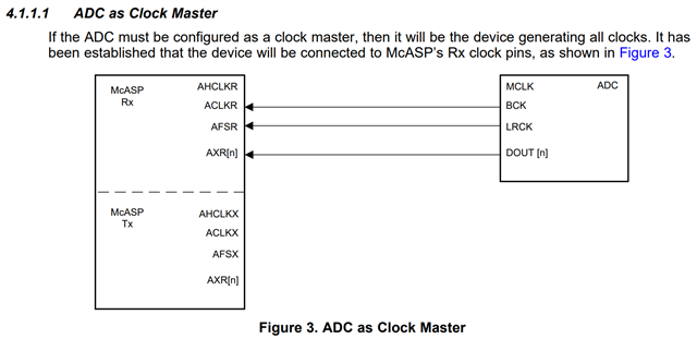
In TI McASP Design Guide, if ADC is configured as a clock master, the clock pins on ADC should connect to McASP’s Rx clock pins, as shown in following Figure.
Then I have modified DTS "k3-j721e-common-proc-board.dts" to configurate McASP0 (ACLKR & AFSR), and set MCASP0_ACLKR & MCASP0_AFSR as INPUT.
mcasp0_pins_default: mcasp0-pins-default {
	pinctrl-single,pins = <
		J721E_IOPAD(0x0B8, PIN_INPUT_PULLDOWN, 12) /* (AE27) PRG0_PRU0_GPO2.MCASP0_ACLKR */
		J721E_IOPAD(0x0BC, PIN_INPUT_PULLDOWN, 12) /* (AD26) PRG0_PRU0_GPO3.MCASP0_AFSR */
		/* J721E_IOPAD(0x0D4, PIN_OUTPUT_PULLDOWN, 12) /* (AB26) prg0_pru0_gpo9.MCASP0_ACLKX */
		/* J721E_IOPAD(0x0D8, PIN_OUTPUT_PULLDOWN, 12) /* (AB25) prg0_pru0_gpo10.MCASP0_AFSX */
		J721E_IOPAD(0x0B0, PIN_OUTPUT_PULLDOWN, 12) /* (AF28) prg0_pru0_gpo0.MCASP0_AXR0 */
		J721E_IOPAD(0x0B4, PIN_INPUT_PULLDOWN, 12) /* (AE28) prg0_pru0_gpo1.MCASP0_AXR1 */

	>;
};
But when I tried to record a raw file on McASP0 port with ALSA command:
arecord -Dplughw:0,1 -d 10 -r 48000 -f S16_LE -t raw /bin/RecordFile
I found MCASP0_ACLKR pin is wtill generating 6.14M colck, shouldn't it be in receiving mode?
The full DTS "k3-j721e-common-proc-board.dts" is shown below:
// SPDX-License-Identifier: GPL-2.0
/*
 * Copyright (C) 2019 Texas Instruments Incorporated - https://www.ti.com/
 */

/dts-v1/;

#include "k3-j721e-som-p0.dtsi"
#include <dt-bindings/gpio/gpio.h>
#include <dt-bindings/input/input.h>
#include <dt-bindings/net/ti-dp83867.h>
#include <dt-bindings/phy/phy-cadence.h>

/ {
	chosen {
		stdout-path = "serial2:115200n8";
		bootargs = "console=ttyS2,115200n8 earlycon=ns16550a,mmio32,0x02800000";
	};

	gpio_keys: gpio-keys {
		compatible = "gpio-keys";
		autorepeat;
		pinctrl-names = "default";
		pinctrl-0 = <&sw10_button_pins_default &sw11_button_pins_default>;

		sw10: sw10 {
			label = "GPIO Key USER1";
			linux,code = <BTN_0>;
			gpios = <&main_gpio0 0 GPIO_ACTIVE_LOW>;
		};

		sw11: sw11 {
			label = "GPIO Key USER2";
			linux,code = <BTN_1>;
			gpios = <&wkup_gpio0 7 GPIO_ACTIVE_LOW>;
		};
	};

	evm_12v0: fixedregulator-evm12v0 {
		/* main supply */
		compatible = "regulator-fixed";
		regulator-name = "evm_12v0";
		regulator-min-microvolt = <12000000>;
		regulator-max-microvolt = <12000000>;
		regulator-always-on;
		regulator-boot-on;
	};

	vsys_3v3: fixedregulator-vsys3v3 {
		/* Output of LMS140 */
		compatible = "regulator-fixed";
		regulator-name = "vsys_3v3";
		regulator-min-microvolt = <3300000>;
		regulator-max-microvolt = <3300000>;
		vin-supply = <&evm_12v0>;
		regulator-always-on;
		regulator-boot-on;
	};

	vsys_5v0: fixedregulator-vsys5v0 {
		/* Output of LM5140 */
		compatible = "regulator-fixed";
		regulator-name = "vsys_5v0";
		regulator-min-microvolt = <5000000>;
		regulator-max-microvolt = <5000000>;
		vin-supply = <&evm_12v0>;
		regulator-always-on;
		regulator-boot-on;
	};

	vdd_mmc1: fixedregulator-sd {
		compatible = "regulator-fixed";
		regulator-name = "vdd_mmc1";
		regulator-min-microvolt = <3300000>;
		regulator-max-microvolt = <3300000>;
		regulator-boot-on;
		enable-active-high;
		vin-supply = <&vsys_3v3>;
		/* gpio = <&exp2 2 GPIO_ACTIVE_HIGH>; */   /*mark by shawn...currently hw set this always on */
	};

	vdd_sd_dv_alt: gpio-regulator-TLV71033 {
		compatible = "regulator-gpio";
		pinctrl-names = "default";
		pinctrl-0 = <&vdd_sd_dv_alt_pins_default>;
		regulator-name = "tlv71033";
		regulator-min-microvolt = <1800000>;
		regulator-max-microvolt = <3300000>;
		regulator-boot-on;
		vin-supply = <&vsys_5v0>;
		/* gpios = <&main_gpio0 117 GPIO_ACTIVE_HIGH>; */   /* mark by shawn...we don't need this pin to select voltage output */
		/* states = <1800000 0x0>, */   /* mark by shawn...our sd power is 3v3 */
		states = <3300000 0x0>,
			 <3300000 0x1>;
	};

	// Enable McASP TDM
	sound0: sound@0 {
		compatible = "ti,j721e-cpb-audio";
		model = "j721e-cpb";

		// ti,cpb-mcasp = <&mcasp10>; // Use McASP10 Interface
		ti,cpb-mcasp = <&mcasp0>; // Use McASP0 Interface
		ti,cpb-codec = <&pcm3168a_1>;

		clocks = <&k3_clks 184 1>,
			 <&k3_clks 184 2>, <&k3_clks 184 4>,
			 <&k3_clks 157 371>,
			 <&k3_clks 157 400>, <&k3_clks 157 401>;
		clock-names = "cpb-mcasp-auxclk",
			      "cpb-mcasp-auxclk-48000", "cpb-mcasp-auxclk-44100",
			      "cpb-codec-scki",
			      "cpb-codec-scki-48000", "cpb-codec-scki-44100";
	};

/*	Bryant Lin modify - 2022-04-18
	cpsw9g_virt_mac: main_r5fss_cpsw9g_virt_mac0 {
		compatible = "ti,j721e-cpsw-virt-mac";
		dma-coherent;
		ti,psil-base = <0x4a00>;
		ti,remote-name = "mpu_1_0_ethswitch-device-0";

		dmas = <&main_udmap 0xca00>,
		       <&main_udmap 0xca01>,
		       <&main_udmap 0xca02>,
		       <&main_udmap 0xca03>,
		       <&main_udmap 0xca04>,
		       <&main_udmap 0xca05>,
		       <&main_udmap 0xca06>,
		       <&main_udmap 0xca07>,
		       <&main_udmap 0x4a00>;
		dma-names = "tx0", "tx1", "tx2", "tx3",
			    "tx4", "tx5", "tx6", "tx7",
			    "rx";

		virt_emac_port {
			ti,label = "virt-port";
			// local-mac-address = [0 0 0 0 0 0];
		};
	};

	cpsw9g_virt_maconly: main-r5fss-cpsw9g-virt-mac1 {
		compatible = "ti,j721e-cpsw-virt-mac";
		dma-coherent;
		ti,psil-base = <0x4a00>;
		ti,remote-name = "mpu_1_0_ethmac-device-1";

		dmas = <&main_udmap 0xca00>,
		       <&main_udmap 0xca01>,
		       <&main_udmap 0xca02>,
		       <&main_udmap 0xca03>,
		       <&main_udmap 0xca04>,
		       <&main_udmap 0xca05>,
		       <&main_udmap 0xca06>,
		       <&main_udmap 0xca07>,
		       <&main_udmap 0x4a00>;
		dma-names = "tx0", "tx1", "tx2", "tx3",
			    "tx4", "tx5", "tx6", "tx7",
			    "rx";

		virt_emac_port {
			ti,label = "virt-port";
			// local-mac-address = [0 0 0 0 0 0];
		};
	};
*/
/*
	transceiver1: can-phy0 {
		compatible = "ti,tcan1043";
		#phy-cells = <0>;
		max-bitrate = <5000000>;
		pinctrl-names = "default";
		pinctrl-0 = <&mcu_mcan0_gpio_pins_default>;
		standby-gpios = <&wkup_gpio0 54 GPIO_ACTIVE_LOW>;
		enable-gpios = <&wkup_gpio0 0 GPIO_ACTIVE_HIGH>;
	};

	transceiver2: can-phy1 {
		compatible = "ti,tcan1042";
		#phy-cells = <0>;
		max-bitrate = <5000000>;
		pinctrl-names = "default";
		pinctrl-0 = <&mcu_mcan1_gpio_pins_default>;
		standby-gpios = <&wkup_gpio0 2 GPIO_ACTIVE_HIGH>;
	};

	transceiver3: can-phy2 {
		compatible = "ti,tcan1043";
		#phy-cells = <0>;
		max-bitrate = <5000000>;
		standby-gpios = <&exp2 7 GPIO_ACTIVE_LOW>;
		enable-gpios = <&exp2 6 GPIO_ACTIVE_HIGH>;
	};

	transceiver4: can-phy3 {
		compatible = "ti,tcan1042";
		#phy-cells = <0>;
		max-bitrate = <5000000>;
		pinctrl-names = "default";
		pinctrl-0 = <&main_mcan2_gpio_pins_default>;
		standby-gpios = <&main_gpio0 127 GPIO_ACTIVE_HIGH>;
	};
*/

	dp_pwr_3v3: fixedregulator-dp-prw {
		compatible = "regulator-fixed";
		regulator-name = "dp-pwr";
		regulator-min-microvolt = <3300000>;
		regulator-max-microvolt = <3300000>;
		//gpio = <&exp4 0 0>;	/* P0 - DP0_PWR_SW_EN */
		enable-active-high;

		/* Always on for now, until dp-connector driver can handle this */
		regulator-always-on;
	};

	dp0: connector {
		compatible = "dp-connector";
		label = "DP0";
		type = "full-size";
		dp-pwr-supply = <&dp_pwr_3v3>;

		port {
			dp_connector_in: endpoint {
				remote-endpoint = <&dp0_out>;
			};
		};
	};
};

&main_pmx0 {
/* Jimmy Wei modify - 2023-05-02 */
	spi0_pins_default: spi0_pins_default {
		pinctrl-single,pins = <
			J721E_IOPAD(0x1c8, PIN_INPUT, 0) /* (AA1) SPI0_CLK */
			J721E_IOPAD(0x1c0, PIN_INPUT, 0) /* (AA2) SPI0_CS0 */
			J721E_IOPAD(0x1c4, PIN_INPUT, 0) /* (Y4) SPI0_CS1 */
			//J721E_IOPAD(0x1f0, PIN_INPUT, 2) /* (AC2) UART0_CTSn.SPI0_CS2 */
			//J721E_IOPAD(0x1f4, PIN_INPUT, 2) /* (AB1) UART0_RTSn.SPI0_CS3 */
			J721E_IOPAD(0x1cc, PIN_INPUT, 0) /* (AB5) SPI0_D0 */
			J721E_IOPAD(0x1d0, PIN_INPUT, 0) /* (AA3) SPI0_D1 */
		>;
	};

/* Sam Chu Modify – 2023-07-12 */
	spi1_pins_default: spi1_pins_default {
		pinctrl-single,pins = <
			J721E_IOPAD(0x1dc, PIN_INPUT, 0) /* (Y1) SPI1_CLK */
			J721E_IOPAD(0x1d4, PIN_INPUT, 0) /* (Y3) SPI1_CS0 */
			//J721E_IOPAD(0x1d8, PIN_INPUT, 0) /* (W4) SPI1_CS1 */
			J721E_IOPAD(0x1e0, PIN_INPUT, 0) /* (Y5) SPI1_D0 */
			J721E_IOPAD(0x1e4, PIN_INPUT, 0) /* (Y2) SPI1_D1 */
		>;
	};

	sw10_button_pins_default: sw10-button-pins-default {
		pinctrl-single,pins = <
			J721E_IOPAD(0x0, PIN_INPUT, 7) /* (AC18) EXTINTn.GPIO0_0 */
		>;
	};

	main_mmc1_pins_default: main-mmc1-pins-default {
		pinctrl-single,pins = <
			J721E_IOPAD(0x254, PIN_INPUT, 0) /* (R29) MMC1_CMD */
			J721E_IOPAD(0x250, PIN_INPUT, 0) /* (P25) MMC1_CLK */
			J721E_IOPAD(0x2ac, PIN_INPUT, 0) /* (P25) MMC1_CLKLB */
			J721E_IOPAD(0x24c, PIN_INPUT, 0) /* (R24) MMC1_DAT0 */
			J721E_IOPAD(0x248, PIN_INPUT, 0) /* (P24) MMC1_DAT1 */
			J721E_IOPAD(0x244, PIN_INPUT, 0) /* (R25) MMC1_DAT2 */
			J721E_IOPAD(0x240, PIN_INPUT, 0) /* (R26) MMC1_DAT3 */
			J721E_IOPAD(0x258, PIN_INPUT, 0) /* (P23) MMC1_SDCD */
			J721E_IOPAD(0x25c, PIN_INPUT, 0) /* (R28) MMC1_SDWP */
		>;
	};

	vdd_sd_dv_alt_pins_default: vdd-sd-dv-alt-pins-default {
		pinctrl-single,pins = <
			//J721E_IOPAD(0x1d8, PIN_INPUT, 7) /* (W4) SPI1_CS1.GPIO0_117 */
			J721E_IOPAD(0x210, PIN_INPUT, 7) /* (W3) MCAN1_RX.GPIO1_3 */
		>;
	};

	main_usbss0_pins_default: main-usbss0-pins-default {
		pinctrl-single,pins = <
			J721E_IOPAD(0x290, PIN_OUTPUT, 0) /* (U6) USB0_DRVVBUS */
			J721E_IOPAD(0x210, PIN_INPUT, 7) /* (W3) MCAN1_RX.GPIO1_3 */
		>;
	};

	main_usbss1_pins_default: main-usbss1-pins-default {
		pinctrl-single,pins = <
			J721E_IOPAD(0x214, PIN_OUTPUT, 4) /* (V4) MCAN1_TX.USB1_DRVVBUS */
		>;
	};

	dp0_pins_default: dp0-pins-default {
		pinctrl-single,pins = <
			J721E_IOPAD(0x1c4, PIN_INPUT, 5) /* SPI0_CS1.DP0_HPD */
		>;
	};

	// main_i2c1_exp4_pins_default: main-i2c1-exp4-pins-default {
	// 	pinctrl-single,pins = <
	// 		J721E_IOPAD(0x230, PIN_INPUT, 7) /* (U2) ECAP0_IN_APWM_OUT.GPIO1_11 */
	// 	>;
	// };

	main_i2c0_pins_default: main-i2c0-pins-default {
		pinctrl-single,pins = <
			J721E_IOPAD(0x220, PIN_INPUT_PULLUP, 0) /* (AC5) I2C0_SCL */
			J721E_IOPAD(0x224, PIN_INPUT_PULLUP, 0) /* (AA5) I2C0_SDA */
		>;
	};

	main_i2c1_pins_default: main-i2c1-pins-default {
		pinctrl-single,pins = <
			J721E_IOPAD(0x228, PIN_INPUT_PULLUP, 0) /* (Y6) I2C1_SCL */
			J721E_IOPAD(0x22c, PIN_INPUT_PULLUP, 0) /* (AA6) I2C1_SDA */
		>;
	};

/* Jimmy Wei modify - 2023-05-02
	main_i2c2_pins_default: main-i2c2-pins-default {
		pinctrl-single,pins = <
			J721E_IOPAD(0x1c8, PIN_INPUT_PULLUP, 2) // (AB5) SPI0_CLK.I2C2_SCL
			J721E_IOPAD(0x1cc, PIN_INPUT_PULLUP, 2) // (AA1) SPI0_D0.I2C2_SDA
		>;
	};
*/

	main_i2c3_pins_default: main-i2c3-pins-default {
		pinctrl-single,pins = <
			J721E_IOPAD(0x270, PIN_INPUT_PULLUP, 4) /* (T26) MMC2_CLK.I2C3_SCL */
			J721E_IOPAD(0x274, PIN_INPUT_PULLUP, 4) /* (T25) MMC2_CMD.I2C3_SDA */
		>;
	};

/* Jimmy Wei modify - 2023-05-02
	main_i2c6_pins_default: main-i2c6-pins-default {
		pinctrl-single,pins = <
			J721E_IOPAD(0x1d0, PIN_INPUT_PULLUP, 2) // (AA3) SPI0_D1.I2C6_SCL
			J721E_IOPAD(0x1e4, PIN_INPUT_PULLUP, 2) // (Y2) SPI1_D1.I2C6_SDA
		>;
	};
*/
	// Add McASP0 PinControl
	mcasp0_pins_default: mcasp0-pins-default {
		pinctrl-single,pins = <
			J721E_IOPAD(0x0B8, PIN_INPUT_PULLDOWN, 12) /* (AE27) PRG0_PRU0_GPO2.MCASP0_ACLKR */
			J721E_IOPAD(0x0BC, PIN_INPUT_PULLDOWN, 12) /* (AD26) PRG0_PRU0_GPO3.MCASP0_AFSR */
			/* J721E_IOPAD(0x0D4, PIN_OUTPUT_PULLDOWN, 12) /* (AB26) prg0_pru0_gpo9.MCASP0_ACLKX */
			/* J721E_IOPAD(0x0D8, PIN_OUTPUT_PULLDOWN, 12) /* (AB25) prg0_pru0_gpo10.MCASP0_AFSX */
			J721E_IOPAD(0x0B0, PIN_OUTPUT_PULLDOWN, 12) /* (AF28) prg0_pru0_gpo0.MCASP0_AXR0 */
			J721E_IOPAD(0x0B4, PIN_INPUT_PULLDOWN, 12) /* (AE28) prg0_pru0_gpo1.MCASP0_AXR1 */

		>;
	};

	mcasp10_pins_default: mcasp10-pins-default {
		pinctrl-single,pins = <
			J721E_IOPAD(0x158, PIN_OUTPUT_PULLDOWN, 12) /* (U23) RGMII5_TX_CTL.MCASP10_ACLKX */
			J721E_IOPAD(0x15c, PIN_OUTPUT_PULLDOWN, 12) /* (U26) RGMII5_RX_CTL.MCASP10_AFSX */
			J721E_IOPAD(0x160, PIN_OUTPUT_PULLDOWN, 12) /* (V28) RGMII5_TD3.MCASP10_AXR0 */
			J721E_IOPAD(0x164, PIN_OUTPUT_PULLDOWN, 12) /* (V29) RGMII5_TD2.MCASP10_AXR1 */
			J721E_IOPAD(0x170, PIN_OUTPUT_PULLDOWN, 12) /* (U29) RGMII5_TXC.MCASP10_AXR2 */
			J721E_IOPAD(0x174, PIN_OUTPUT_PULLDOWN, 12) /* (U25) RGMII5_RXC.MCASP10_AXR3 */
			J721E_IOPAD(0x198, PIN_INPUT_PULLDOWN, 12) /* (V25) RGMII6_TD1.MCASP10_AXR4 */
			J721E_IOPAD(0x19c, PIN_INPUT_PULLDOWN, 12) /* (W27) RGMII6_TD0.MCASP10_AXR5 */
			J721E_IOPAD(0x1a0, PIN_INPUT_PULLDOWN, 12) /* (W29) RGMII6_TXC.MCASP10_AXR6 */
		>;
	};

	audi_ext_refclk2_pins_default: audi-ext-refclk2-pins-default {
		pinctrl-single,pins = <
			J721E_IOPAD(0x1a4, PIN_OUTPUT, 3) /* (W26) RGMII6_RXC.AUDIO_EXT_REFCLK2 */
		>;
	};

	main_mcan0_pins_default: main-mcan0-pins-default {
		pinctrl-single,pins = <
			J721E_IOPAD(0x208, PIN_INPUT, 0) /* (W5) MCAN0_RX */
			J721E_IOPAD(0x20c, PIN_OUTPUT, 0) /* (W6) MCAN0_TX */
		>;
	};

	main_mcan2_pins_default: main-mcan2-pins-default {
		pinctrl-single,pins = <
			J721E_IOPAD(0x01f0, PIN_INPUT, 3) /* (AC2) MCAN2_RX.GPIO0_123 */
			J721E_IOPAD(0x01f4, PIN_OUTPUT, 3) /* (AB1) MCAN2_TX.GPIO0_124 */
		>;
	};

	main_mcan2_gpio_pins_default: main-mcan2-gpio-pins-default {
		pinctrl-single,pins = <
			J721E_IOPAD(0x200, PIN_INPUT, 7) /* (AC4) UART1_CTSn.GPIO0_127 */
		>;
	};
};

&wkup_pmx0 {
	sw11_button_pins_default: sw11-button-pins-default {
		pinctrl-single,pins = <
			J721E_WKUP_IOPAD(0xcc, PIN_INPUT, 7) /* (G28) WKUP_GPIO0_7 */
		>;
	};

	mcu_fss0_ospi1_pins_default: mcu-fss0-ospi1-pins-default {
		pinctrl-single,pins = <
			J721E_WKUP_IOPAD(0x34, PIN_OUTPUT, 0) /* (F22) MCU_OSPI1_CLK */
			J721E_WKUP_IOPAD(0x50, PIN_OUTPUT, 0) /* (C22) MCU_OSPI1_CSn0 */
			J721E_WKUP_IOPAD(0x40, PIN_INPUT, 0) /* (D22) MCU_OSPI1_D0 */
			J721E_WKUP_IOPAD(0x44, PIN_INPUT, 0) /* (G22) MCU_OSPI1_D1 */
			J721E_WKUP_IOPAD(0x48, PIN_INPUT, 0) /* (D23) MCU_OSPI1_D2 */
			J721E_WKUP_IOPAD(0x4c, PIN_INPUT, 0) /* (C23) MCU_OSPI1_D3 */
			J721E_WKUP_IOPAD(0x3c, PIN_INPUT, 0) /* (B23) MCU_OSPI1_DQS */
			J721E_WKUP_IOPAD(0x38, PIN_INPUT, 0) /* (A23) MCU_OSPI1_LBCLKO */
		>;
	};

	mcu_cpsw_pins_default: mcu-cpsw-pins-default {
		pinctrl-single,pins = <
			J721E_WKUP_IOPAD(0x0058, PIN_OUTPUT, 0) /* MCU_RGMII1_TX_CTL */
			J721E_WKUP_IOPAD(0x005c, PIN_INPUT, 0) /* MCU_RGMII1_RX_CTL */
			J721E_WKUP_IOPAD(0x0060, PIN_OUTPUT, 0) /* MCU_RGMII1_TD3 */
			J721E_WKUP_IOPAD(0x0064, PIN_OUTPUT, 0) /* MCU_RGMII1_TD2 */
			J721E_WKUP_IOPAD(0x0068, PIN_OUTPUT, 0) /* MCU_RGMII1_TD1 */
			J721E_WKUP_IOPAD(0x006c, PIN_OUTPUT, 0) /* MCU_RGMII1_TD0 */
			J721E_WKUP_IOPAD(0x0078, PIN_INPUT, 0) /* MCU_RGMII1_RD3 */
			J721E_WKUP_IOPAD(0x007c, PIN_INPUT, 0) /* MCU_RGMII1_RD2 */
			J721E_WKUP_IOPAD(0x0080, PIN_INPUT, 0) /* MCU_RGMII1_RD1 */
			J721E_WKUP_IOPAD(0x0084, PIN_INPUT, 0) /* MCU_RGMII1_RD0 */
			J721E_WKUP_IOPAD(0x0070, PIN_OUTPUT, 0) /* MCU_RGMII1_TXC */
			J721E_WKUP_IOPAD(0x0074, PIN_INPUT, 0) /* MCU_RGMII1_RXC */
		>;
	};

	mcu_mdio_pins_default: mcu-mdio1-pins-default {
		pinctrl-single,pins = <
			J721E_WKUP_IOPAD(0x008c, PIN_OUTPUT, 0) /* MCU_MDIO0_MDC */
			J721E_WKUP_IOPAD(0x0088, PIN_INPUT, 0) /* MCU_MDIO0_MDIO */
		>;
	};

	mcu_mcan0_pins_default: mcu-mcan0-pins-default {
		pinctrl-single,pins = <
			J721E_WKUP_IOPAD(0xac, PIN_INPUT, 0) /* (C29) MCU_MCAN0_RX */
			J721E_WKUP_IOPAD(0xa8, PIN_OUTPUT, 0) /* (D29) MCU_MCAN0_TX */
		>;
	};

	mcu_mcan0_gpio_pins_default: mcu-mcan0-gpio-pins-default {
		pinctrl-single,pins = <
			J721E_WKUP_IOPAD(0xb0, PIN_INPUT, 7) /* (F26) WKUP_GPIO0_0 */
			J721E_WKUP_IOPAD(0x98, PIN_INPUT, 7) /* (E28) MCU_SPI0_D1.WKUP_GPIO0_54 */
		>;
	};

	mcu_mcan1_pins_default: mcu-mcan1-pins-default {
		pinctrl-single,pins = <
			J721E_WKUP_IOPAD(0xc4, PIN_INPUT, 0) /* (G24) WKUP_GPIO0_5.MCU_MCAN1_RX */
			J721E_WKUP_IOPAD(0xc0, PIN_OUTPUT, 0) /* (G25) WKUP_GPIO0_4.MCU_MCAN1_TX */
		>;
	};

	mcu_mcan1_gpio_pins_default: mcu-mcan1-gpio-pins-default {
		pinctrl-single,pins = <
			J721E_WKUP_IOPAD(0xb8, PIN_INPUT, 7) /* (F28) WKUP_GPIO0_2 */
		>;
	};
};

&wkup_uart0 {
	/* Wakeup UART is used by System firmware */
	//status = "reserved";	Modify by Bryant Lin 2022-04-18
	status = "disabled";
};

&main_uart0 {
	power-domains = <&k3_pds 146 TI_SCI_PD_SHARED>;
};

&main_uart3 {
	/* UART not brought out */
	status = "disabled";
};

&main_uart5 {
	/* UART not brought out */
	status = "disabled";
};

&main_uart6 {
	/* UART not brought out */
	status = "disabled";
};

&main_uart7 {
	/* UART not brought out */
	status = "disabled";
};

&main_uart8 {
	/* UART not brought out */
	status = "disabled";
};

&main_uart9 {
	/* UART not brought out */
	status = "disabled";
};

&main_gpio2 {
	status = "disabled";
};

&main_gpio3 {
	status = "disabled";
};

&main_gpio4 {
	status = "disabled";
};

&main_gpio5 {
	status = "disabled";
};

&main_gpio6 {
	status = "disabled";
};

&main_gpio7 {
	status = "disabled";
};

&wkup_gpio1 {
	status = "disabled";
};

&main_sdhci0 {
	/* eMMC */
	non-removable;
	ti,driver-strength-ohm = <50>;
	disable-wp;
};

&main_sdhci1 {
	/* SD/MMC */
	vmmc-supply = <&vdd_mmc1>;
	vqmmc-supply = <&vdd_sd_dv_alt>;
	pinctrl-names = "default";
	pinctrl-0 = <&main_mmc1_pins_default>;
	ti,driver-strength-ohm = <50>;
	disable-wp;
};

&main_sdhci2 {
	/* Unused */
	status = "disabled";
};

&usb_serdes_mux {
	idle-states = <1>, <0>; /* USB0 to SERDES3, USB1 to SERDES1 */
};

&serdes_ln_ctrl {
	idle-states = <J721E_SERDES0_LANE0_PCIE0_LANE0>, <J721E_SERDES0_LANE1_QSGMII_LANE2>,
		      <J721E_SERDES1_LANE0_PCIE1_LANE0>, <J721E_SERDES1_LANE1_PCIE1_LANE1>,
		      <J721E_SERDES2_LANE0_PCIE2_LANE0>, <J721E_SERDES2_LANE1_PCIE2_LANE1>,
		      <J721E_SERDES3_LANE0_USB3_0_SWAP>, <J721E_SERDES3_LANE1_USB3_0>,
		      <J721E_SERDES4_LANE0_EDP_LANE0>, <J721E_SERDES4_LANE1_EDP_LANE1>,
		      <J721E_SERDES4_LANE2_EDP_LANE2>, <J721E_SERDES4_LANE3_EDP_LANE3>;
};

&serdes_wiz3 {
	typec-dir-gpios = <&main_gpio1 3 GPIO_ACTIVE_HIGH>;
	typec-dir-debounce-ms = <700>;	/* TUSB321, tCCB_DEFAULT 133 ms */
};

&serdes3 {
	serdes3_usb_link: phy@0 {
		reg = <0>;
		cdns,num-lanes = <2>;
		#phy-cells = <0>;
		cdns,phy-type = <PHY_TYPE_USB3>;
		resets = <&serdes_wiz3 1>, <&serdes_wiz3 2>;
	};
};

&usbss0 {
	pinctrl-names = "default";
	pinctrl-0 = <&main_usbss0_pins_default>;
	ti,vbus-divider;
};

&usb0 {
	dr_mode = "otg";
	maximum-speed = "super-speed";
	phys = <&serdes3_usb_link>;
	phy-names = "cdns3,usb3-phy";
};

&usbss1 {
	pinctrl-names = "default";
	pinctrl-0 = <&main_usbss1_pins_default>;
	ti,usb2-only;
};

&usb1 {
	dr_mode = "host";
	maximum-speed = "high-speed";
};

&ospi1 {
	pinctrl-names = "default";
	pinctrl-0 = <&mcu_fss0_ospi1_pins_default>;

	flash@0{
		compatible = "jedec,spi-nor";
		reg = <0x0>;
		spi-tx-bus-width = <1>;
		spi-rx-bus-width = <4>;
		spi-max-frequency = <40000000>;
		cdns,tshsl-ns = <60>;
		cdns,tsd2d-ns = <60>;
		cdns,tchsh-ns = <60>;
		cdns,tslch-ns = <60>;
		cdns,read-delay = <2>;
		#address-cells = <1>;
		#size-cells = <1>;
	};
};

/*	Bryant Lin modify - 2022-04-20
&tscadc0 {
	adc {
		ti,adc-channels = <0 1 2 3 4 5 6 7>;
	};
};

&tscadc1 {
	adc {
		ti,adc-channels = <0 1 2 3 4 5 6 7>;
	};
};
*/

&main_i2c0 {
	pinctrl-names = "default";
	pinctrl-0 = <&main_i2c0_pins_default>;
	clock-frequency = <400000>;

	exp1: gpio@20 {
		compatible = "ti,tca6416";
		reg = <0x20>;
		gpio-controller;
		#gpio-cells = <2>;
	};

	exp2: gpio@22 {
		compatible = "ti,tca6424";
		reg = <0x22>;
		gpio-controller;
		#gpio-cells = <2>;

		p08-hog {
			/* P10 - PM_I2C_CTRL_OE */
			gpio-hog;
			gpios = <8 GPIO_ACTIVE_HIGH>;
			output-high;
			line-name = "CTRL_PM_I2C_OE";
		};

		p09-hog {
			/* P11 - MCASP/TRACE_MUX_S0 */
			gpio-hog;
			gpios = <9 GPIO_ACTIVE_HIGH>;
			output-low;
			line-name = "MCASP/TRACE_MUX_S0";
		};

		p10-hog {
			/* P12 - MCASP/TRACE_MUX_S1 */
			gpio-hog;
			gpios = <10 GPIO_ACTIVE_HIGH>;
			output-high;
			line-name = "MCASP/TRACE_MUX_S1";
		};
	};
};

&main_i2c1 {
	pinctrl-names = "default";
	pinctrl-0 = <&main_i2c1_pins_default>;
	clock-frequency = <400000>;
/*
	exp4: gpio@20 {
		compatible = "ti,tca6408";
		reg = <0x20>;
		gpio-controller;
		#gpio-cells = <2>;
		pinctrl-names = "default";
		pinctrl-0 = <&main_i2c1_exp4_pins_default>;
		interrupt-parent = <&main_gpio1>;
		interrupts = <11 IRQ_TYPE_EDGE_FALLING>;
		interrupt-controller;
		#interrupt-cells = <2>;
	};
*/
};

/* Jimmy Wei modify - 2023-05-02
&main_i2c2 {
	pinctrl-names = "default";
	pinctrl-0 = <&main_i2c2_pins_default>;
	clock-frequency = <100000>;

	ina226@40 {
		compatible = "ti,ina226";
		reg = <0x40>;
		shunt-resistor = <50>;
	};

	ina226@41 {
		compatible = "ti,ina226";
		reg = <0x41>;
		shunt-resistor = <50>;
	};

	ina226@42 {
		compatible = "ti,ina226";
		reg = <0x42>;
		shunt-resistor = <50>;
	};

	ina226@43 {
		compatible = "ti,ina226";
		reg = <0x43>;
		shunt-resistor = <50>;
	};

	ina226@44 {
		compatible = "ti,ina226";
		reg = <0x44>;
		shunt-resistor = <50>;
	};

	ina226@45 {
		compatible = "ti,ina226";
		reg = <0x45>;
		shunt-resistor = <50>;
	};

	ina226@46 {
		compatible = "ti,ina226";
		reg = <0x46>;
		shunt-resistor = <50>;
	};

	ina226@47 {
		compatible = "ti,ina226";
		reg = <0x48>;
		shunt-resistor = <10000>;
	};

	ina226@48 {
		compatible = "ti,ina226";
		reg = <0x49>;
		shunt-resistor = <50>;
	};

	ina226@4a {
		compatible = "ti,ina226";
		reg = <0x4a>;
		shunt-resistor = <50>;
	};

	ina226@4b {
		compatible = "ti,ina226";
		reg = <0x4b>;
		shunt-resistor = <50>;
	};
};
*/

&k3_clks {
	// Confiure AUDIO_EXT_REFCLK2 pin as output
	pinctrl-names = "default";
	pinctrl-0 = <&audi_ext_refclk2_pins_default>;
};

&main_i2c3 {
	pinctrl-names = "default";
	pinctrl-0 = <&main_i2c3_pins_default>;
	clock-frequency = <400000>;

	exp3: gpio@20 {
		compatible = "ti,tca6408";
		reg = <0x20>;
		gpio-controller;
		#gpio-cells = <2>;
	};

	pcm3168a_1: audio-codec@44 {
		compatible = "ti,pcm3168a";
		reg = <0x44>;

		#sound-dai-cells = <1>;

		reset-gpios = <&exp3 0 GPIO_ACTIVE_LOW>;

		// C_AUDIO_REFCLK2 -> RGMII6_RXC (W26)
		clocks = <&k3_clks 157 371>;
		clock-names = "scki";

		// HSDIV3_16FFT_MAIN_4_HSDIVOUT2_CLK -> REFCLK2
		assigned-clocks = <&k3_clks 157 371>;
		assigned-clock-parents = <&k3_clks 157 400>;
		assigned-clock-rates = <24576000>; // for 48KHz

		VDD1-supply = <&vsys_3v3>;
		VDD2-supply = <&vsys_3v3>;
		VCCAD1-supply = <&vsys_5v0>;
		VCCAD2-supply = <&vsys_5v0>;
		VCCDA1-supply = <&vsys_5v0>;
		VCCDA2-supply = <&vsys_5v0>;
	};
};

/* Jimmy Wei modify - 2023-05-02
&main_i2c6 {
	pinctrl-names = "default";
	pinctrl-0 = <&main_i2c6_pins_default>;
	clock-frequency = <400000>;

	// exp5: gpio@20 {
	// 	compatible = "ti,tca6408";
	// 	reg = <0x20>;
	// 	gpio-controller;
	// 	#gpio-cells = <2>;
	// };
};
*/

&mcu_cpsw {
	pinctrl-names = "default";
	pinctrl-0 = <&mcu_cpsw_pins_default &mcu_mdio_pins_default>;
};

&davinci_mdio {
	phy0: ethernet-phy@0 {
		reg = <0>;
		ti,rx-internal-delay = <DP83867_RGMIIDCTL_2_00_NS>;
		ti,fifo-depth = <DP83867_PHYCR_FIFO_DEPTH_4_B_NIB>;
	};
};

&cpsw_port1 {
	phy-mode = "rgmii-rxid";
	phy-handle = <&phy0>;
};

&dss {
	/*
	 * These clock assignments are chosen to enable the following outputs:
	 *
	 * VP0 - DisplayPort SST
	 * VP1 - DPI0
	 * VP2 - DSI
	 * VP3 - DPI1
	 */

	assigned-clocks = <&k3_clks 152 1>,
			  <&k3_clks 152 4>,
			  <&k3_clks 152 9>,
			  <&k3_clks 152 13>;
	assigned-clock-parents = <&k3_clks 152 2>,	/* PLL16_HSDIV0 */
				 <&k3_clks 152 6>,	/* PLL19_HSDIV0 */
				 <&k3_clks 152 11>,	/* PLL18_HSDIV0 */
				 <&k3_clks 152 18>;	/* PLL23_HSDIV0 */
};

&dss_ports {
	port@0 {
		reg = <0>;

		dpi0_out: endpoint {
			remote-endpoint = <&dp0_in>;
		};
	};
};

&mhdp {
	pinctrl-names = "default";
	pinctrl-0 = <&dp0_pins_default>;
};

&dp0_ports {
	#address-cells = <1>;
	#size-cells = <0>;

	port@0 {
		reg = <0>;
		dp0_in: endpoint {
			remote-endpoint = <&dpi0_out>;
		};
	};

	port@4 {
		reg = <4>;
		dp0_out: endpoint {
			remote-endpoint = <&dp_connector_in>;
		};
	};
};

// Enable McASP0 Interface
&mcasp0 {
	#sound-dai-cells = <0>;

	pinctrl-names = "default";
	pinctrl-0 = <&mcasp0_pins_default>;

	op-mode = <0>; /* I2S/DIT ops mode. 0 for I2S mode. 1 for DIT mode used for S/PDIF, IEC60958-1, and AES-3 formats. */
	tdm-slots = <8>;
	auxclk-fs-ratio = <256>;

	serial-dir = <	/* 0: INACTIVE, 1: TX, 2: RX */
		1 2 0 0
		0 0 0 0
	>;
	tx-num-evt = <8>;
	rx-num-evt = <8>;
};

&mcasp1 {
	status = "disabled";
};

&mcasp2 {
	status = "disabled";
};

&mcasp3 {
	status = "disabled";
};

&mcasp4 {
	status = "disabled";
};

&mcasp5 {
	status = "disabled";
};

&mcasp6 {
	status = "disabled";
};

&mcasp7 {
	status = "disabled";
};

&mcasp8 {
	status = "disabled";
};

&mcasp9 {
	status = "disabled";
};

&mcasp10 {
	#sound-dai-cells = <0>;

	pinctrl-names = "default";
	pinctrl-0 = <&mcasp10_pins_default>;

	op-mode = <0>;          /* MCASP_IIS_MODE */
	tdm-slots = <8>;
	auxclk-fs-ratio = <256>;

	serial-dir = <	/* 0: INACTIVE, 1: TX, 2: RX */
		1 1 1 1
		2 2 2 0
	>;
	tx-num-evt = <8>;
	rx-num-evt = <8>;
};

&mcasp11 {
	status = "disabled";
};

&cmn_refclk1 {
	clock-frequency = <100000000>;
};

&wiz0_pll1_refclk {
	assigned-clocks = <&wiz0_pll1_refclk>;
	assigned-clock-parents = <&cmn_refclk1>;
};

&wiz0_refclk_dig {
	assigned-clocks = <&wiz0_refclk_dig>;
	assigned-clock-parents = <&cmn_refclk1>;
};

&wiz1_pll1_refclk {
	assigned-clocks = <&wiz1_pll1_refclk>;
	assigned-clock-parents = <&cmn_refclk1>;
};

&wiz1_refclk_dig {
	assigned-clocks = <&wiz1_refclk_dig>;
	assigned-clock-parents = <&cmn_refclk1>;
};

&wiz2_pll1_refclk {
	assigned-clocks = <&wiz2_pll1_refclk>;
	assigned-clock-parents = <&cmn_refclk1>;
};

&wiz2_refclk_dig {
	assigned-clocks = <&wiz2_refclk_dig>;
	assigned-clock-parents = <&cmn_refclk1>;
};

&cmn_refclk1 {
	clock-frequency = <100000000>;
};

/*
&serdes0 {
	assigned-clocks = <&serdes0 CDNS_SIERRA_PLL_CMNLC>, <&serdes0 CDNS_SIERRA_PLL_CMNLC1>;
	assigned-clock-parents = <&wiz0_pll1_refclk>, <&wiz0_pll1_refclk>;

	serdes0_pcie_link: phy@0 {
		reg = <0>;
		cdns,num-lanes = <1>;
		#phy-cells = <0>;
		cdns,phy-type = <PHY_TYPE_PCIE>;
		resets = <&serdes_wiz0 1>;
	};

	serdes0_qsgmii_link: phy@1 {
		reg = <1>;
		cdns,num-lanes = <1>;
		#phy-cells = <0>;
		cdns,phy-type = <PHY_TYPE_QSGMII>;
		resets = <&serdes_wiz0 2>;
	};

};

&serdes1 {
	assigned-clocks = <&serdes1 CDNS_SIERRA_PLL_CMNLC>;
	assigned-clock-parents = <&wiz1_pll1_refclk>;

	serdes1_pcie_link: phy@0 {
		reg = <0>;
		cdns,num-lanes = <2>;
		#phy-cells = <0>;
		cdns,phy-type = <PHY_TYPE_PCIE>;
		resets = <&serdes_wiz1 1>, <&serdes_wiz1 2>;
	};
};

&serdes2 {
	assigned-clocks = <&serdes2 CDNS_SIERRA_PLL_CMNLC>;
	assigned-clock-parents = <&wiz2_pll1_refclk>;

	serdes2_pcie_link: phy@0 {
		reg = <0>;
		cdns,num-lanes = <2>;
		#phy-cells = <0>;
		cdns,phy-type = <PHY_TYPE_PCIE>;
		resets = <&serdes_wiz2 1>, <&serdes_wiz2 2>;
	};
};
*/

&pcie0_rc {
	status = "disabled";	// Modify by Bryant - 2022-04-18
	// reset-gpios = <&exp1 6 GPIO_ACTIVE_HIGH>;
	// phys = <&serdes0_pcie_link>;
	// phy-names = "pcie-phy";
	// num-lanes = <1>;
};

&pcie1_rc {
	status = "disabled";	// Modify by Bryant - 2022-04-18
	// reset-gpios = <&exp1 2 GPIO_ACTIVE_HIGH>;
	// phys = <&serdes1_pcie_link>;
	// phy-names = "pcie-phy";
	// num-lanes = <2>;
};

&pcie2_rc {
	status = "disabled";	// Modify by Bryant - 2022-04-18
	// reset-gpios = <&exp2 20 GPIO_ACTIVE_HIGH>;
	// phys = <&serdes2_pcie_link>;
	// phy-names = "pcie-phy";
	// num-lanes = <2>;
};

&pcie0_ep {
	status = "disabled";	// Modify by Bryant - 2022-04-18
	// phys = <&serdes0_pcie_link>;
	// phy-names = "pcie-phy";
	// num-lanes = <1>;
	// status = "disabled";
};

&pcie1_ep {
	status = "disabled";	// Modify by Bryant - 2022-04-18
	// phys = <&serdes1_pcie_link>;
	// phy-names = "pcie-phy";
	// num-lanes = <2>;
	// status = "disabled";
};

&pcie2_ep {
	status = "disabled";	// Modify by Bryant - 2022-04-18
	// phys = <&serdes2_pcie_link>;
	// phy-names = "pcie-phy";
	// num-lanes = <2>;
	// status = "disabled";
};

&pcie3_rc {
	status = "disabled";
};

&pcie3_ep {
	status = "disabled";
};

/* uart2 assigned to cpsw9g eth-switch fw running on remote CPU core */
&main_uart2 {
	status = "disabled";
};

&mcu_mcan0 {
	status = "disabled";	// Modify by Bryant - 2022-04-18
	// pinctrl-names = "default";
	// pinctrl-0 = <&mcu_mcan0_pins_default>;
	// phys = <&transceiver1>;
};

&mcu_mcan1 {
	status = "disabled";	// Modify by Bryant - 2022-04-18
	// pinctrl-names = "default";
	// pinctrl-0 = <&mcu_mcan1_pins_default>;
	// phys = <&transceiver2>;
};

&main_mcan0 {
	status = "disabled";	// Modify by Bryant - 2022-04-18
	// pinctrl-names = "default";
	// pinctrl-0 = <&main_mcan0_pins_default>;
	// phys = <&transceiver3>;
};

&main_mcan1 {
	status = "disabled";
};

&main_mcan2 {
	status = "disabled";	// Modify by Bryant - 2022-04-18
	// pinctrl-names = "default";
	// pinctrl-0 = <&main_mcan2_pins_default>;
	// phys = <&transceiver4>;
};

&main_mcan3 {
	status = "disabled";
};

&main_mcan4 {
	status = "disabled";
};

&main_mcan5 {
	status = "disabled";
};

&main_mcan6 {
	status = "disabled";
};

&main_mcan7 {
	status = "disabled";
};

&main_mcan8 {
	status = "disabled";
};

&main_mcan9 {
	status = "disabled";
};

&main_mcan10 {
	status = "disabled";
};

&main_mcan11 {
	status = "disabled";
};

&main_mcan12 {
	status = "disabled";
};

&main_mcan13 {
	status = "disabled";
};

&csi0_port0 {
	status = "disabled";
};

&csi0_port1 {
	status = "disabled";
};

&csi0_port2 {
	status = "disabled";
};

&csi0_port3 {
	status = "disabled";
};

&csi0_port4 {
	status = "disabled";
};

&main_ehrpwm0 {
	status = "disabled";
};

&main_ehrpwm1 {
	status = "disabled";
};

&main_ehrpwm2 {
	status = "disabled";
};

&main_ehrpwm3 {
	status = "disabled";
};

&main_ehrpwm4 {
	status = "disabled";
};

&main_ehrpwm5 {
	status = "disabled";
};

//Jimmy Wei modify - 2023-05-02
&main_spi0 {
    pinctrl-names = "default";
    pinctrl-0 = <&spi0_pins_default>;
    status="okay";

    spidev@0 {
       spi-max-frequency = <24000000>;
       reg = <0>;
       compatible = "linux,spidev";
	};
};

//Sam Chu modify - 2023-07-12
&main_spi1 {
    pinctrl-names = "default";
    pinctrl-0 = <&spi1_pins_default>;
    status="okay";
    spidev@0 {
       spi-max-frequency = <24000000>;
       reg = <0>;
       compatible = "linux,spidev";
	};
};
Does anyone know how to configure J721e McASP0 as Slave Mode?
Thank you very much!!
Shawn