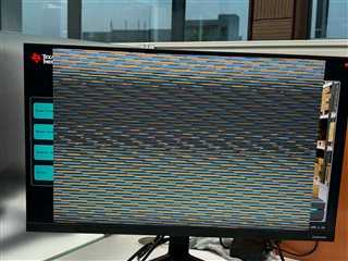
This thread has been locked.

If you have a related question, please click the "Ask a related question" button in the top right corner. The newly created question will be automatically linked to this question.

SK-TDA4VM: Command for custom resolution by IMX219

Part Number: SK-TDA4VM


Hi,

I have below command to click picture from imx219 on TI board.
gst-launch-1.0 v4l2src device=/dev/video2 io-mode=5 ! queue leaky=2 ! \
video/x-bayer, width=1920, height=1080, framerate=30/1, format=rggb ! \
tiovxisp sink_0::device=/dev/v4l-subdev2 sensor-name="SENSOR_SONY_IMX219_RPI" \
dcc-isp-file=/opt/imaging/imx219/dcc_viss_1920x1080.bin \
sink_0::dcc-2a-file=/opt/imaging/imx219/dcc_2a_1920x1080.bin format-msb=7 ! \
tiovxmultiscaler ! \
video/x-raw, format=NV12, width=1920, height=1080, framerate=30/1 ! \
jpegenc ! multifilesink sync=False location=../data/output/images/output_image1.jpg

Now, I want to click pictures of custom resolution like 800*1200. I checked all the bin files, I think I can only use below resolutions
root@tda4vm-sk:/opt/imaging/imx219# ls
dcc_2a.bin   dcc_viss.bin
dcc_2a_10b.bin   dcc_viss_10b.bin
dcc_2a_10b_1280x720.bin   dcc_viss_10b_1280x720.bin
dcc_2a_10b_1640x1232.bin  dcc_viss_10b_1640x1232.bin
dcc_2a_10b_1920x1080.bin  dcc_viss_10b_1920x1080.bin
dcc_2a_10b_320x240.bin   dcc_viss_10b_320x240.bin
dcc_2a_10b_640x480.bin   dcc_viss_10b_640x480.bin
dcc_2a_1280x720.bin   dcc_viss_1280x720.bin
dcc_2a_1640x1232.bin   dcc_viss_1640x1232.bin
dcc_2a_1920x1080.bin   dcc_viss_1920x1080.bin
dcc_2a_320x240.bin   dcc_viss_320x240.bin
dcc_2a_640x480.bin   dcc_viss_640x480.bin

Please help to get a picture of any resolution e.g. 800*1200. Width=800 and Height=1200

  • Hi Tarun,

    There is an ISP tuning guide that outlines the steps for doing this: https://www.ti.com/lit/an/sprad86/sprad86.pdf

    The referenced imaging software can be found here: https://git.ti.com/cgit/processor-sdk/imaging/tree/tools/default_DCC_profile_gen?h=main

    Although IMX219 is supported, it looks like the script for that sensor is currently missing. I have asked our imaging team to add the required files, but in the meantime you could use the existing files in this folder as reference.

    Thank you,

    Fabiana

  • Hi Fabiana,

    Thanks for the prompt reply.

    I followed same steps as mentioned in https://www.ti.com/lit/an/sprad86/sprad86.pdf

    I first created imx219_properties.txt file for imx219 for resolution 800*1200 in imaging/tools/configs/. as below:

    SENSOR_ID 219
    PRJ_DIR ../imx219_output
    SENSOR_NAME imx219
    SENSOR_DCC_NAME IMX219SENSOR_WIDTH 800
    SENSOR_HEIGHT 1200# 0=RGGB; 1=GRBG; 2=GBRG; 3=BGGR, 4=MONO
    COLOR_PATTERN 1# sensor mode: 0 for linear (no decompanding), 1 for WDR (decompanding)
    WDR_MODE 1# raw sensor image BIT_DEPTH: it may be 8, 10, or 12 for linear sensors; typically 12 for WDR mode because of companding
    BIT_DEPTH 12# WDR BIT_DEPTH: WDR raw sensor image bitdepth after decompanding, typically 20 or 24
    WDR_BIT_DEPTH 20# WDR decompanding knee points (comma separated without spaces in between)
    WDR_KNEE_X 0,512,1024,1536,2048,2560,3072,3584,3840,3904,3968,4032,4092,4095
    WDR_KNEE_Y 0,512,1024,2048,4096,8192,16384,32768,65536,131072,262144,524288,1048575,1048575# Sensor black level to subtract before decompanding (for linear sensors only and some Sony WDR sensors)
    BLACK_PRE  0# Sensor black level to subtract after decompanding (for most WDR sensors and all linear sensors)
    BLACK_POST  168# GAMMA value for compressing 20/24-bit WDR raw to 16-bit ISP internal
    # typically around 50 (0.5) for 24-bit WDR sensors and 70 (0.7) for 20-bit sensors
    GAMMA_PRE 70# LSB location for H3A input bit range (from bit-H3A_INPUT_LSB to bit-H3A_INPUT_LSB+9)
    H3A_INPUT_LSB 2

    Then, using imaging/tools/default_DCC_profile_gen/scripts/ctt_def_xml_gen.py, I created .xml files. These got created in imaging/tools/default_DCC_profile_gen/imx219_output/dcc_xmls/wdr.

    Now, after executing generate_dcc.sh , I created bin files in imaging/tools/default_DCC_profile_gen/imx219_output/dcc_bins folder as dcc_2a_wdr.bin and dcc_viss_wdr.bin.

    I copied these bin files to my TI board in /opt/imaging/imx219/ folder and ran following command:

    gst-launch-1.0 -v v4l2src num-buffers=5 device=/dev/video2 io-mode=dmabuf-import ! video/x-bayer, width=800, height=1200, framerate=30/1, format=rggb10 ! tiovxisp sink_0::device=/dev/v4l-subdev2 sensor-name="SENSOR_SONY_IMX219_RPI" dcc-isp-file=/opt/imaging/imx219/dcc_viss_wdr.bin sink_0::dcc-2a-file=/opt/imaging/imx219/dcc_2a_wdr.bin format-msb=9 ! video/x-raw, format=NV12, width=800, height=1200, framerate=30/1 ! jpegenc ! multifilesink location=../opt/edgeai-gst-apps/imx219-image-1.jpg

    and I got below error:

    APP: Init ... !!!
    MEM: Init ... !!!
    MEM: Initialized DMA HEAP (fd=5) !!!
    MEM: Init ... Done !!!
    IPC: Init ... !!!
    IPC: Init ... Done !!!
    REMOTE_SERVICE: Init ... !!!
    REMOTE_SERVICE: Init ... Done !!!
    546.057049 s: GTC Frequency = 200 MHz
    APP: Init ... Done !!!
    546.057113 s: VX_ZONE_INIT:Enabled
    546.057123 s: VX_ZONE_ERROR:Enabled
    546.057130 s: VX_ZONE_WARNING:Enabled
    546.057910 s: VX_ZONE_INIT:[tivxInitLocal:130] Initialization Done !!!
    546.058072 s: VX_ZONE_INIT:[tivxHostInitLocal:93] Initialization Done for HOST !!!
    Setting pipeline to PAUSED ...
    Pipeline is live and does not need PREROLL ...
    /GstPipeline:pipeline0/GstV4l2Src:v4l2src0.GstPad:src: caps = video/x-bayer, width=(int)800, height=(int)1200, framerate=(fraction)30/1, format=(string)rggb10, colorimetry=(string)2:4:7:1, interlace-mode=(string)progressive
    /GstPipeline:pipeline0/GstCapsFilter:capsfilter0.GstPad:src: caps = video/x-bayer, width=(int)800, height=(int)1200, framerate=(fraction)30/1, format=(string)rggb10, colorimetry=(string)2:4:7:1, interlace-mode=(string)progressive
    /GstPipeline:pipeline0/GstTIOVXISP:tiovxisp0.GstTIOVXIspPad:sink_0: caps = video/x-bayer, width=(int)800, height=(int)1200, framerate=(fraction)30/1, format=(string)rggb10, colorimetry=(string)2:4:7:1, interlace-mode=(string)progressive
    /GstPipeline:pipeline0/GstCapsFilter:capsfilter0.GstPad:sink: caps = video/x-bayer, width=(int)800, height=(int)1200, framerate=(fraction)30/1, format=(string)rggb10, colorimetry=(string)2:4:7:1, interlace-mode=(string)progressive
    Setting pipeline to PLAYING ...
    New clock: GstSystemClock

    Please, help with this.

  • Hi Tarun,

    As mentioned in section 6.2.1, the configuration must match the format that the sensor is set as. For IMX219, set the color pattern to RGGB and bit depth to 10. Keep in mind that IMX219 is a linear sensor so change the properties accordingly. To change the format and resolution of your sensor, use media-ctl --set-v4l2 as outlined here: https://software-dl.ti.com/jacinto7/esd/processor-sdk-linux-sk-tda4vm/09_01_00/exports/docs/linux/Foundational_Components/Kernel/Kernel_Drivers/Camera/CSI2RX.html#utilities-to-interact-with-the-driver

    I am awaiting the imx219_properties.txt from our imaging team and will share that with you as soon as it is available.

    Thank you,

    Fabiana

  • See the following example imx219_properties.txt file:

    SENSOR_ID 219
    PRJ_DIR ../imx219_output
    SENSOR_NAME imx219
    SENSOR_DCC_NAME IMX219
    
    SENSOR_WIDTH 1920
    SENSOR_HEIGHT 1080
    
    # 0=RGGB; 1=GRBG; 2=GBRG; 3=BGGR, 4=MONO
    COLOR_PATTERN 0
    
    # sensor mode: 0 for linear (no decompanding), 1 for WDR (decompanding)
    WDR_MODE 0
    
    # raw sensor image BIT_DEPTH: it may be 8, 10, or 12 for linear sensors; typically 12 for WDR mode because of companding
    BIT_DEPTH 10
    
    # WDR BIT_DEPTH: WDR raw sensor image bitdepth after decompanding, typically 20 or 24
    WDR_BIT_DEPTH 10
    
    # WDR decompanding knee points (comma separated without spaces in between)
    WDR_KNEE_X 0,512,1408,2176,4095,65535
    WDR_KNEE_Y 0,2048,16384,65536,1048063,1048063
    
    # Sensor black level to subtract before decompanding (for linear sensors only and some Sony WDR sensors)
    BLACK_PRE  64
    
    # Sensor black level to subtract after decompanding (for most WDR sensors and all linear sensors)
    BLACK_POST  0
    
    # GAMMA value for compressing 20/24-bit WDR raw to 16-bit ISP internal
    # typically around 50 (0.5) for 24-bit WDR sensors and 70 (0.7) for 20-bit sensors
    GAMMA_PRE 70
    
    # LSB location for H3A input bit range (from bit-H3A_INPUT_LSB to bit-H3A_INPUT_LSB+9) 
    H3A_INPUT_LSB 0

    Thank you,

    Fabiana

  • Hi Fabiana,

    Thanks for the prompt reply.

    I followed same steps as mentioned by you I changed my imx219_properties.txt .

    here's the updated version:

    imx219_properties.txt

    SENSOR_ID 219
    PRJ_DIR ../../../sensor_drv/src/imx219_output
    SENSOR_NAME SENSOR_SONY_IMX219_RPI
    SENSOR_DCC_NAME IMX219
    
    SENSOR_WIDTH 800
    SENSOR_HEIGHT 1200
    
    # 0=RGGB; 1=GRBG; 2=GBRG; 3=BGGR, 4=MONO
    COLOR_PATTERN 0
    
    # sensor mode: 0 for linear (no decompanding), 1 for WDR (decompanding)
    WDR_MODE 0
    
    # raw sensor image BIT_DEPTH: it may be 8, 10, or 12 for linear sensors; typically 12 for WDR mode because of companding
    BIT_DEPTH 10
    
    # WDR BIT_DEPTH: WDR raw sensor image bitdepth after decompanding, typically 20 or 24
    WDR_BIT_DEPTH 10
    
    # WDR decompanding knee points (comma separated without spaces in between)
    WDR_KNEE_X 0,512,1408,2176,4095,65535
    WDR_KNEE_Y 0,2048,16384,65536,1048063,1048063
    
    # Sensor black level to subtract before decompanding (for linear sensors only and some Sony WDR sensors)
    BLACK_PRE  64
    
    # Sensor black level to subtract after decompanding (for most WDR sensors and all linear sensors)
    BLACK_POST  0
    
    # GAMMA value for compressing 20/24-bit WDR raw to 16-bit ISP internal
    # typically around 50 (0.5) for 24-bit WDR sensors and 70 (0.7) for 20-bit sensors
    GAMMA_PRE 70
    
    # LSB location for H3A input bit range (from bit-H3A_INPUT_LSB to bit-H3A_INPUT_LSB+9) 
    H3A_INPUT_LSB 0

    After updating this I followed all the steps like mentioned in https://www.ti.com/lit/an/sprad86/sprad86.pdf I ran the python script which creates xml files after that I created dcc binary files .

    When I am using "media-ctl" command to set the camera format consistent with the properties in the initial configuration file,

    Its not working as if the command is wrong. Here's the command which i am running:

    media-ctl --set-v4l2 '"SENSOR_SONY_IMX219_RPI 4-0010":0 [fmt:SRGGB_1X8/800x1200@1/30]

    I will provide to the details of my camera which is running on tda4vm-sk .
    Camera details:
    CSI Camera 1 detected
    device = /dev/video2
    name = imx219
    format = [fmt:SRGGB8_1X8/1920x1080]
    subdev_id = /dev/v4l-subdev2
    isp_required = yes


    Full sensor name :
    SENSOR_SONY_IMX219_RPI

    Please provide me the exact command to run so that i can set my camera format with the properties in initial configuration file .
    Also provide me the commands to make camera live and click image on 800x1200 resolution . The names of

    bin dcc files generated are dcc_2a.bin and dcc_viss.bin.


  • Hello Tarun,

    You will also need to make changes to the following script: /opt/edgeai-gst-apps/scripts/setup_cameras.sh. This script is ran upon boot and will execute the command media-ctl --set-v4l2 command with default values, overriding any changes made. Go to line 268 and make this change:

    IMX219_CAM_FMT='[fmt:SRGGB8_1X8/800x1200]'

    After doing this, run ./setup_cameras.sh to make the change. Next, I suggest renaming the binaries to dcc_2a_800x1200.bin and dcc_viss_800x1200.bin and placing them with the other binaries in the following directory: /opt/imaging/imx219. To save frames as jpg files, run the following GStreamer command:

    gst-launch-1.0 v4l2src device=/dev/video2 io-mode=5 ! queue leaky=2 ! \
    video/x-bayer, width=800, height=1200, framerate=30/1, format=rggb ! \
    tiovxisp sink_0::device=/dev/v4l-subdev2 sensor-name="SENSOR_SONY_IMX219_RPI" \
    dcc-isp-file=/opt/imaging/imx219/dcc_viss_800x1200.bin \
    sink_0::dcc-2a-file=/opt/imaging/imx219/dcc_2a_800x1200.bin format-msb=7 ! \
    tiovxmultiscaler ! \
    video/x-raw, format=NV12, width=1920, height=1080, framerate=30/1 ! \
    jpegenc ! multifilesink sync=False location=../data/output/images/output_image_%04d.jpg

    Thank you,

    Fabiana

  • Hi Fabiana, Thanks for the help.

    I made the required change in /scripts/setup_cameras.sh and ran the camera open command which gave below output.

    Just to make sure my .bin files are correct I created it for 640x480 and replaced the already existing bin files. It worked fine. That made me convinced that I am creating bin files the correct way but it is working only for few predefined resolutions like 640x480 but not for resolutions like 800x1200.

    I think there are some more changes in settings required to work with custom resolution. Please help.

  • Hi Tarun,

    Could you share what camera open command you ran? What resolution is your display? Could you see if 1200x800 resolution is successful while I discuss with our imaging team? If 1200x800 is possible, you could rotate the image to get the desired view.

    Thank you,

    Fabiana

  • Camera open command:

    gst-launch-1.0 v4l2src device=/dev/video2 io-mode=5 ! queue leaky=2 ! \
    video/x-bayer, width=800, height=1200, framerate=30/1, format=rggb ! \
    tiovxisp sink_0::device=/dev/v4l-subdev2 sensor-name="SENSOR_SONY_IMX219_RPI" \
    dcc-isp-file=/opt/imaging/imx219/dcc_viss_800x1200.bin \
    sink_0::dcc-2a-file=/opt/imaging/imx219/dcc_2a_800x1200.bin format-msb=7 ! \
    tiovxmultiscaler ! \
    video/x-raw, format=NV12, width=800, height=1200, framerate=30/1 ! \
    kmssink driver-name=tidss sync=false

    NO , 1200x800 resolution was also not successful , I have tried it too.

  • Hi Tarun,

    If IMX219_CAM_FMT='[fmt:SRGGB8_1X8/800x1200]', could you try running this pipeline instead:

    gst-launch-1.0 v4l2src device=/dev/video2 io-mode=5 ! queue leaky=2 ! \
    video/x-bayer, width=800, height=1200, framerate=30/1, format=rggb ! \
    tiovxisp sink_0::device=/dev/v4l-subdev2 sensor-name="SENSOR_SONY_IMX219_RPI" \
    dcc-isp-file=/opt/imaging/imx219/dcc_viss_800x1200.bin \
    sink_0::dcc-2a-file=/opt/imaging/imx219/dcc_2a_800x1200.bin format-msb=7 ! \
    tiovxmultiscaler ! \
    video/x-raw, format=NV12, width=1920, height=1080, framerate=30/1 ! \
    kmssink driver-name=tidss sync=false

    If IMX219_CAM_FMT='[fmt:SRGGB8_1X8/1200x800]', could you try running this pipeline:

    gst-launch-1.0 v4l2src device=/dev/video2 io-mode=5 ! queue leaky=2 ! \
    video/x-bayer, width=1200, height=800, framerate=30/1, format=rggb ! \
    tiovxisp sink_0::device=/dev/v4l-subdev2 sensor-name="SENSOR_SONY_IMX219_RPI" \
    dcc-isp-file=/opt/imaging/imx219/dcc_viss_1200x800.bin \
    sink_0::dcc-2a-file=/opt/imaging/imx219/dcc_2a_1200x800.bin format-msb=7 ! \
    tiovxmultiscaler ! \
    video/x-raw, format=NV12, width=1920, height=1080, framerate=30/1 ! \
    kmssink driver-name=tidss sync=false

    Thank you,

    Fabiana

  • Hi Fabiana, Thanks for the help.

    The commands you are giving have output resolution as 1920x1080 , I want it such that the input and output resolution should be 800x1200. 

    when i am running this command:

    gst-launch-1.0 v4l2src device=/dev/video2 io-mode=5 ! queue leaky=2 ! \
    video/x-bayer, width=800, height=1200, framerate=30/1, format=rggb ! \
    tiovxisp sink_0::device=/dev/v4l-subdev2 sensor-name="SENSOR_SONY_IMX219_RPI" \
    dcc-isp-file=/opt/imaging/imx219/dcc_viss_800x1200.bin \
    sink_0::dcc-2a-file=/opt/imaging/imx219/dcc_2a_800x1200.bin format-msb=7 ! \
    tiovxmultiscaler ! \
    video/x-raw, format=NV12, width=800, height=1200, framerate=30/1 ! \
    kmssink driver-name=tidss sync=false

    its not giving any image just the image I showed .

    similar thing is happening when I am running this command :

    gst-launch-1.0 v4l2src device=/dev/video2 io-mode=5 ! queue leaky=2 ! \
    video/x-bayer, width=1200, height=800, framerate=30/1, format=rggb ! \
    tiovxisp sink_0::device=/dev/v4l-subdev2 sensor-name="SENSOR_SONY_IMX219_RPI" \
    dcc-isp-file=/opt/imaging/imx219/dcc_viss_1200x800.bin \
    sink_0::dcc-2a-file=/opt/imaging/imx219/dcc_2a_1200x800.bin format-msb=7 ! \
    tiovxmultiscaler ! \
    video/x-raw, format=NV12, width=1200, height=800, framerate=30/1 ! \
    kmssink driver-name=tidss sync=false

    Please give me command or any other change that is required in settings or anything?


  • Hi Tarun,

    My apologies, it appears I had left out the mosiac part of the pipeline. Could you please try the following for 1200x800?

    gst-launch-1.0 v4l2src device=/dev/video2 io-mode=5 ! queue leaky=2 ! \
    video/x-bayer, width=1200, height=800, framerate=30/1, format=rggb ! \
    tiovxisp sink_0::device=/dev/v4l-subdev2 sensor-name="SENSOR_SONY_IMX219_RPI" \
    dcc-isp-file=/opt/imaging/imx219/dcc_viss_1200x800.bin \
    sink_0::dcc-2a-file=/opt/imaging/imx219/dcc_2a_1200x800.bin format-msb=7 ! \
    tiovxmultiscaler target=0 ! \
    video/x-raw, width=1200, height=800 ! mosaic.sink_0 \
    tiovxmosaic name=mosaic sink_0::start_x="<360>" sink_0::starty="<140>" ! \
    video/x-raw, format=NV12, width=1920, height=1080, framerate=30/1 ! \
    queue ! kmssink driver-name=tidss sync=false

    Thank you,

    Fabiana