Because of the holidays, TI E2E™ design support forum responses will be delayed from Dec. 25 through Jan. 2. Thank you for your patience.

This thread has been locked.

If you have a related question, please click the "Ask a related question" button in the top right corner. The newly created question will be automatically linked to this question.

AM625: emmc HS200 Occasional IO errors

Part Number: AM625

Hi TI,
         We use  SDK: 09_01_00_08 , Kernel Version: 6.1.46-rt13 in our custom board.
         We use emmc sdhci0 on speed HS200 ,then to test Repeatedly power on and off.

        1.
             we found sometimes  sdhci0 will happened error about in one hour ,detail log as Attached file.

             sdhci-am654 fa10000.mmc: __mmc_blk_ioctl_cmd: cmd error -84

             I/O error, dev mmcblk0, sector 25533296 op 0x0:(READ) flags 0x80700 phys_seg 32 prio class 2
        2. 
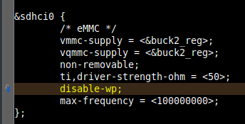
              we found if change devices-tree sdhci0 max-frequency to 100M ,  run one day until now not happened this error.

             but it case mmc HS200 read speed down to about 85~89MB/s. 

        could you fix this Error?


315-mmc-IO-error.log

  • Hi Mars,

    If the issue only happens in 200MHz in HS200 mode, but not in 100MHz, it sounds to be hardware related.

    I am routing your query to our MMC hardware expert to check the hardware design first.

  • It is not clear if you are having problems with read or write operations. I suggest you perform some tests where you write data patterns into the eMMC device at the slower transfer rate, then try to read same data back at the higher transfer rate and compare the data patterns. This should help identify if you are having problems with reads or writes.

    Did you design your PCB to be compliant with the parameters defined in the Timing Conditions table found in the HS200 timing section of the datasheet?

    Have you checked the timing relationship of clock to data during read transactions?  Did you check the signal quality of the signals during read and write transactions to ensure that are no unexpected signal distortion at the respective receiver?

    Regards,
    Paul

  • Hi peaves,

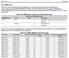
    I'm a colleague of mars. Is the information in the image below the parameters defined in the Timing Conditions table? Or could you provide the tables?

     
  • No,

    The Timing Conditions table is located near the beginning of the MMC0 timing section and contains the PCB Connectivity Requirements for each data transfer mode.

    Regards,
    Paul

  • Paul, 

    Customer is evaluating SI on eMMC. 

    There are two following questions from HW RD. 

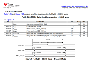
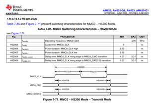
    (1)There is only Transmit mode的switching characteristic for HS200 in AM62x Data Sheet,

    Is there more specify timing request table for it? 

    (2)What's the internal resister value for internal pull up R on eMMC Data 1~ Data 7 as it shows in eMMC boot mode. 

    BR, Rich

  • The HS200 data transfer mode requires the read data path to be tuned for optimum timing. This means HS200 read timing varies based on the final tuning results. Therefore, it is not possible to define the device input requirements for HS200.

    The eMMC standard requires an eMMC device to have internal pull-up resistors on DAT[7:1] turned on by default. The eMMC device will turn off the DAT[3:1] resistors once the device is switched to 4-bit mode, or will turn off the DAT[7:1] resistors once the device is switched to 8-bit mode. At this point the eMMC host must turn on its respective internal pull resistors, or external pulls must be used.

    We require external pulls on the CLK, CMD, and DAT0 signals to hold the eMMC inputs in a valid logic state because the AM62x IOs are turned off by default. The eMMC device internal resistors will hold the DAT[7:1] inputs in a valid logic state until software has initialized the peripheral.

    The eMMC boot code never enables the internal resistors on CLK, CMD, or DAT0 because they should already have external pulls as described above. However, it must turn on the AM62x DAT[7:1] internal resistors because the eMMC device will turn its internal resistors off once it enters 8-bit mode.

    The pull resistance value of the AM62x internal pulls is defined in the SDIO Electrical Characteristics table found in the datasheet. The pull resistance value of the eMMC device internal pulls is defined in the eMMC standard. The pull resistance of the external pull resistors should be selected to be compliant to the eMMC standard.

    FYI: There is an error in the eMMC Pin Usage table you inserted above. There is no pin named MMC0_CLKLB.

    Regards,
    Paul

  • Hi Paul,

    So I need to check this two design?

    (1)Design external pulls on CLK, CMD, and DAT0 signals

    (2)Enables internal pulls on DAT1-7 after eMMC device enters 4-bit or 8-bit mode

    And how could I check if AM62 internal pull resistors enable or disable?Is there any register store the state of internal pull resistors?

  • We recommend an external pull-down on CLK, an external pull-up on CMD, and an external pull-up on DAT0. The resistors values should be in the range of 15k to 50k ohms.

    You only enable the AM62x internal pulls which are turned off in the eMMC device. The eMMC device will only turn off the DAT[3:1] resistors when the device is switched to 4-bit mode, so you would only need to turn on the AM62x internal pulls for DAT[3:1] when operating in 4-bit mode.  You would turn on the AM62x internal pulls for DAT[7:1] when operating in 8-bit mode.

    The AM62x internal pulls are controlled via the respective PADCONFIG register.

    Regards,
    Paul

  • Hi Peaves,
    You would turn on the AM62x internal pulls for DAT[7:1] when operating in 8-bit mode.
    Is it mean to change k3-am62x-sk-common.dtsi as follow can do it, or we need change PADCONFIG register in emmc driver?
    Is there a convenient tool that can check the PADCONFIG register value of the board in use?

    main_mmc0_pins_default: main-mmc0-pins-default {
    pinctrl-single,pins = <
    AM62X_IOPAD(0x220, PIN_INPUT, 0) /* (Y3/V3) MMC0_CMD */
    AM62X_IOPAD(0x218, PIN_INPUT, 0) /* (AB1/Y1) MMC0_CLK */
    AM62X_IOPAD(0x214, PIN_INPUT, 0) /* (AA2/V2) MMC0_DAT0 */
    AM62X_IOPAD(0x210, PIN_INPUT_PULLUP, 0) /* (AA1/V1) MMC0_DAT1 */
    AM62X_IOPAD(0x20c, PIN_INPUT_PULLUP, 0) /* (AA3/W2) MMC0_DAT2 */
    AM62X_IOPAD(0x208, PIN_INPUT_PULLUP, 0) /* (Y4/W1) MMC0_DAT3 */
    AM62X_IOPAD(0x204, PIN_INPUT_PULLUP, 0) /* (AB2/Y2) MMC0_DAT4 */
    AM62X_IOPAD(0x200, PIN_INPUT_PULLUP, 0) /* (AC1/W3) MMC0_DAT5 */
    AM62X_IOPAD(0x1fc, PIN_INPUT_PULLUP, 0) /* (AD2/W4) MMC0_DAT6 */
    AM62X_IOPAD(0x1f8, PIN_INPUT_PULLUP, 0) /* (AC2/V4) MMC0_DAT7 */
    >;
    };

  • I only provide hardware support and not familiar with how you modify software to read or write the PADCONFIG registers. I will need to assign the thread back to Bin, so he can answer this question.

    Regards,
    Paul

  • Hi Mars,

    If your Linux filesystem has command 'devmem2', you can use it to read PADCONFIG registers. devmem2 is provided in the Processor SDK default root filesystem.

  • Hi Bin,

    We add external pulls on the CLK, CMD, and DAT0 signals in 16.2KOhm.

    The problem changed from MMC IO error to another as shown below log.

    The system stopped after "NOTICE: BL31: v2.9(rNOTICE: BL31: Built : 09:34:15, Aug 24 2023".

    U-Boot SPL 2023.04-g576b2c98c0 (Mar 11 2024 - 07:42:03 +0000)
    SYSFW ABI: 3.1 (firmware rev 0x0009 '9.1.8--v09.01.08 (Kool Koala)')
    SPL initial stack usage: 13384 bytes
    Trying to boot from MMC1
    Authentication passed
    Authentication passed
    Authentication passed
    Authentication passed
    Authentication passed
    Starting ATF on ARM64 core...

    NOTICE: BL31: v2.9(rNOTICE: BL31: Built : 09:34:15, Aug 24 2023

  • Hi Bin,

    I summarized the tests I did and the results:

    (1)Origianl:

    Design=>external pulls on the CMD and DAT0 signals in 10KOhm. CLK has no external pull down resister.

    Result=>MMC IO error

    Frequency=>We test repeated power on and off, MMC IO error occurs every 50 times.

    (2)

    Design=>external pulls on the CLK, CMD, and DAT0 signals in 16.2KOhm.

    Result=>error occurred during spl as described in my last letter.

    Frequency=>We test repeated power on and off, error occurs every 200 times.

    Now we are trying that "external pulls on the CLK, CMD, and DAT0 signals in 16.2KOhm" and "turn on the AM62x internal pulls for DAT[7:1] when operating in 8-bit mode".

    The number of errors decreased, but the problems changed.

  • Hi HsinYi,

    NOTICE: BL31: v2.9(rNOTICE: BL31: Built : 09:34:15, Aug 24 2023

    Boot stopping here means tiboot3.bin failed to load tispl.bin from eMMC. Now the eMMC read fails in the early booting process - in U-Boot, instead of in kernel as described in your original report.

    I will defer to our hardware expert for comments.

  • Hi Bin & Paul,

    (3)The result of test 3

    Design=>external pulls on the CLK, CMD, and DAT0 signals in 16.2KOhm" and "turn on the AM62x internal pulls for DAT[7:1] when operating in 8-bit mode

    Result=>error same as test 2 occurred (tiboot3.bin failed to load tispl.bin from eMMC)

    Frequency=>We test repeated power on and off, error occurs every 200 times.

    Is there any way to let me know more information?

  • Paul, 

    MMC CLK trace length is longer than CMD and DAT0 pin around 50 mils and MMC_ LK is longer DAT1~DAT7 for 75 mils. 

    Will the trace length difference cause problem in HS200 when it works fine in HS100?

    BR, Rich 

  • The datasheet defines a max Propagation delay mismatch across all traces of 8ps when operating in HS200 mode. There is a good chance the 75 mils difference in trace length will exceed the 8ps limit, so this could be causing or contributing to the problem.

    Regards,
    Paul

  • I'm concerned your addition of pull resistors has made the problem worse. The initial boot load seemed to be working before and your boot problem was associated with Linux boot. Now the problem is occurring with the initial boot loader. Was the PCB modified to add these resistors. If so, can you describe how the PCB was modified or send photos of the modifications?

    Regards,
    Paul

  • Rich, All,

    can you please review this post here. There have been recently discovered issues with HS200/HS400 modes in the context of SDK v9.1 and SDK v9.2 in which ITAPDLY calibration values don't get applied, leading to various PHY-level breakdowns that manifest themselves in bit and CRC errors, just as shown in the OP. The post has a solution to try out.

    https://e2e.ti.com/support/processors-group/processors/f/processors-forum/1344972/am623-issues-with-sandisk-emmc-entering-hs200-mode/5124827#5124827

    Regards, Andreas