Other Parts Discussed in Thread: TDA4VM
Hi, Champ
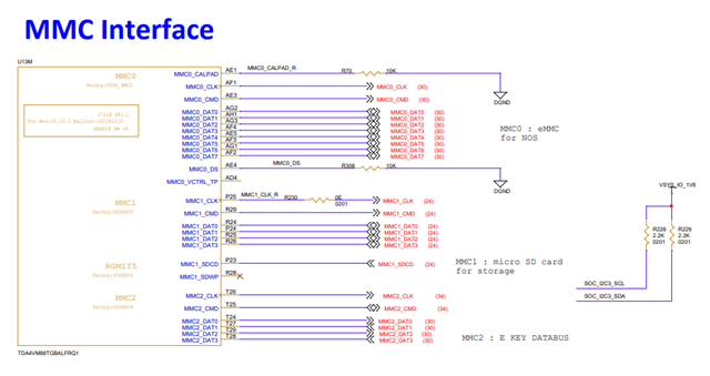
we are developing board based on SK-TDA4VM, MMC connection is planned to change as follows for custom use.
MMCSD0 : eMMC flash (MTFC8GAMALBH-AAT) for BOOT/NOS.
MMCSD1 : micro SD card for storage such as image data
MMCSD2 : E key data lane
Is resource of MMCSDx allocation for eMMC / mSD / E key supported simultaneously?
Specially is it possible to boot TDA4VM by eMMC flash?
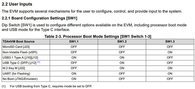
Could you let us know how to set SW/HW to boot via eMMC Flash in SK-TDA4VM.?
I wonder if we can set eMMC Boot by setting [SW1] which is already located on the board. .