This thread has been locked.

If you have a related question, please click the "Ask a related question" button in the top right corner. The newly created question will be automatically linked to this question.

AM6442: PTP and PPS via PRU subsystem

Part Number: AM6442
Other Parts Discussed in Thread: AM625

Dear TI team,

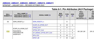
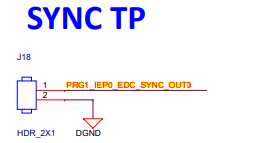
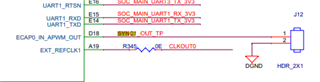
On our AM6442 we have a PTP synchronization over a switched Ethernet connection, where HSR or PRP will be running, so the PTP packets will come in one of the PRU subsystems. We want to generate a PPS signal based on this synchronization and mux it onto a pin, from which we will feed external PLLs.

- Which pin can I use?
- Is it the CPTS peripheral, which will handle the synchronization and the PPS generation?
- How do I have to change the device tree file? I tried something similar on an AM625, there the patch in the attachment worked, but I don't understand it. How do I do something similar on the AM6442? Note that on the AM625 we had PTP running over "normal" Ethernet, here we have it running over a PRU subsystem (probably on HSR).

Kind regards,

Leon

diff --git a/arch/arm64/boot/dts/ti/k3-am625-sk.dts b/arch/arm64/boot/dts/ti/k3-am625-sk.dts
index 83525949aafd..f27cac1fac02 100644
--- a/arch/arm64/boot/dts/ti/k3-am625-sk.dts
+++ b/arch/arm64/boot/dts/ti/k3-am625-sk.dts
@@ -147,6 +147,7 @@ AM62X_IOPAD(0x174, PIN_OUTPUT, 0) /* (AD21) RGMII2_TD2 */
 			AM62X_IOPAD(0x178, PIN_OUTPUT, 0) /* (AC20) RGMII2_TD3 */
 			AM62X_IOPAD(0x168, PIN_OUTPUT, 0) /* (AE21) RGMII2_TXC */
 			AM62X_IOPAD(0x164, PIN_OUTPUT, 0) /* (AA19) RGMII2_TX_CTL */
+			AM62X_IOPAD(0x1F0, PIN_OUTPUT, 1) /* (A18) EXT_REFCLK1.SYNC1_OUT Leon: added here for test */
 		>;
 	};
 
@@ -371,6 +372,8 @@ cpsw_cpts: cpsw-cpts {
 		pinctrl-single,pins = <
 			/* pps [cpsw cpts genf1] in17 -> out12 [cpsw cpts hw3_push] */
 			K3_TS_OFFSET(12, 17)
+			/* pps [cpsw cpts genf1] in17 -> out21 [cpsw cpts SYNC1_OUT] */
+			K3_TS_OFFSET(21, 17)
 			>;
 	};
 };

  • Hello Leon,

    Just to clarify, are you using an AM64x EVM or a custom board? Which Linux SDK version are you currently using?

    I'm see that most of the resources on CPTS are in reference to CPSW based CPTS including the dts files for SK-AM64x and AM64x EVM...I will need more time to research into how CPTS is integrated for PRU Ethernet.

    In the meantime, here are some resources for enabling PPS from CPSW based CPTS.

    If you are using AM64x EVM, using pin D18 could be an option to get PPS according to https://e2e.ti.com/support/processors-group/processors/f/processors-forum/1253565/am6442-gpevm-how-to-check-1-pps where it is connected to the J12 header on the EVM. Please note that D18 is by default pin-muxed to ECAP0_IN_APWM_OUT instead of SYNC0_OUT.

    If you are using SK-AM64x you might find this link useful for getting PPS to a physical pin https://e2e.ti.com/support/processors-group/processors/f/processors-forum/1300940/am6442-1-pps-from-sk-am64b/4940035?tisearch=e2e-sitesearch&keymatch=%25252525252520user%2525252525253A576780#4940035  Please note that in order to activate the PPS signal, you would need to use the testptp tool under /usr/bin/kselftests which is currently not available in SDK 9.0 or 9.1. The testptp tool does exist in SDK 8.6. 

    From a Linux perspective, the CPTS module "exports a kernel interface for specific clock drivers and a PTP clock API user space interface..." according to https://software-dl.ti.com/processor-sdk-linux-rt/esd/AM64X/latest/exports/docs/linux/Foundational_Components/Kernel/Kernel_Drivers/Network/CPSW-PTP.html?highlight=ptp#setup

    I suspect that the patch for AM625 was for routing "out21" to SYNC1_OUT signal which is likely pin-muxed to a pin. This way, the PPS signal can also be routed out of the CPTS Time Sync Router instead of just routing back to the CPTS to timestamp the PPS signal (what line 16 is doing in the patch). You can probably try searching in the AM625 datasheet for "SYNC1_OUT" and see which pin number it's pin-muxed for.

    -Daolin

  • Upon reading over https://e2e.ti.com/support/processors-group/processors/f/processors-forum/1309841/am6442-ptp-slave-on-pru, it seems like IEP is the module that handles timestamp capture for PRU ethernet.

    I don't immediately see any examples on how to enable timestamp capture through IEP (whether through existing SDK documentation or through the SK or EVM dts files), I will have to discuss with the team internally to find out more details.

    -Daolin

  • Hi Leon,

    This resource might be of interest to you to enable 1-PPS on PRU_ICSSG ethernet: https://software-dl.ti.com/processor-sdk-linux-rt/esd/AM64X/latest/exports/docs/linux/Foundational_Components/PRU-ICSS/Linux_Drivers/PRU_ICSSG_Ethernet.html?highlight=tsn#pps-pulse-per-second-support

    One thing I'm trying to investigate is that the "PRG0_IEP0_EDC_SYNC_OUT0" signal is pin-muxed to a pin on the HSE header on the AM64x-EVM which is not easy to directly measure with an oscilloscope, unless you have an HSE connector/cable. I'm not sure if this is okay for your purposes of feeding this PPS signal to external PLLs. 

    Please let me know if you find this helpful...

    -Daolin

  • Hello Daolin,

    I am using the AM64x EVM with the most recent Linux SDK. However, since my question is just about the hardware of the SoC, does this have an influence?

    Thank you for the text about how to generate the PPS. I still don't know how to find out on which SoC ball I get the signal. From the EVM datasheet I see on page 48, that PRG0_IEP0_EDC_SYNC_OUT0 is taken from SoC ball W1 and PRG0_IEP0_EDC_SYNC_OUT1 from ball U1. Are those the SoC balls I need to connect to when designing my own board? How do I know which one of the two?

    You write that pin D18 is connected to the PPS. In the manual I see something completely different (see attachment, taken from page 50). Do we mean the same thing?

    I'd be glad if you found out about the mechanism (CPTS / IEP) behind time synch / PPS via PTP on PRU.

    Kind regards,

    Leon

  • Hi Leon,

    The version of Linux SDK is not very relevant to your specific question here; I generally ask this question to a better idea of what resources you are working with (i.e. what SDK documentation version, which corresponds to the Linux SDK version, you might be looking at)

    -->" I still don't know how to find out on which SoC ball I get the signal. From the EVM datasheet I see on page 48, that PRG0_IEP0_EDC_SYNC_OUT0 is taken from SoC ball W1 and PRG0_IEP0_EDC_SYNC_OUT1 from ball U1. Are those the SoC balls I need to connect to when designing my own board? How do I know which one of the two?"

    Both the PRG0_IEP0_EDC_SYNC_OUT0 and PRG0_IEP0_EDC_SYNC_OUT1 signals are synchronization signals generated by the IEP (industrial ethernet sync) module and can be directly mapped to output signals for external devices to use. Additional details about this can be found in the AM6442 TRM "6.4.13.2.6 PRU_ICSSG IEP Sync0/Sync1 Module". I believe you should be able to map either signal to a pin/external device of your choice when designing your own board. 

    -->"You write that pin D18 is connected to the PPS. In the manual I see something completely different (see attachment, taken from page 50). Do we mean the same thing?"

    I'm looking at the datasheet for AM64x Rev.F and I don't see ball number D18 being connected to the signal name you indicate on page 50 (see below). Try using the datasheet from the product page for AM6442: https://www.ti.com/product/AM6442 

    -->"I'd be glad if you found out about the mechanism (CPTS / IEP) behind time synch / PPS via PTP on PRU."

    Could you elaborate on what you mean by mechanism? CPTS is the module that handles timestamping for CPSW ethernet while IEP is the module that handles timestamping for PRU_ICSSG ethernet. Both are capable of 1PPS support via PTP but the former does it through CPSW and the latter does it through PRU ethernet.

    --------------------------------------

    After some research, I can see there are two options you can take to get 1-PPS signal generated by IEP (PRU ethernet) on a pin with the AM64x-EVM 

    1. Use the default AM64x-EVM device tree file which already includes pin-muxing W7 to signal PRG1_IEP0_EDC_SYNC_OUT0. Note that this is a different signal from the PRG0_IEP0_EDC_SYNC_OUT0 I was investigating earlier. This signal on W7 is already broken out to header J18 that you can directly measure with an oscilloscope to see if 1-PPS shows up after following the instructions in https://software-dl.ti.com/processor-sdk-linux-rt/esd/AM64X/latest/exports/docs/linux/Foundational_Components/PRU-ICSS/Linux_Drivers/PRU_ICSSG_Ethernet.html?highlight=pru_icssg#pps-pulse-per-second-support 

    One thing to note here is that there is a known signal integrity issue with this pin when both RGMII ports are active which can lead to the 1-PPS signal to be cut short. If this is a concern you may try option 2.

    //Pin-mux snippet from AM64x-EVM DTS file
    ....
    	icssg1_iep0_pins_default: icssg1-iep0-pins-default {
    		pinctrl-single,pins = <
    			AM64X_IOPAD(0x0104, PIN_OUTPUT, 2) /* (W7) PRG1_PRU0_GPO19.PRG1_IEP0_EDC_SYNC_OUT0 */
    		>;
    	};
    };

    2. Route one of the "pr1_edcX_syncY_out" signals from the list below as an input to the Time Sync Router module which can route to the "SYNC0_OUT" signal. The SYNC0_OUT signal can be pinmuxed to ball D18 which leads to a header on J12. The schematic will show J12 is connected to "SYNC1_OUT" which is incorrect, it should be "SYNC0_OUT". I provided a snippet of what I think should be modified on the AM64x-EVM dts file to enable signal "pr1_edc0_sync0_out" to be routed to the "SYNC0_OUT" pin through the time sync router. Please note that I haven't tried this out myself yet so please let me know if you run into issues if you try this.

    // Change pinmux from 0 to 1 for D18 to enable SYNC0_OUT
    main_ecap0_pins_default: main-ecap0-pins-default {
    		pinctrl-single,pins = <
    			AM64X_IOPAD(0x0270, PIN_INPUT, 1) /* (D18) SYNC0_OUT */
    		>;
    	};
    
    // Change the existing timesync_router sub-node from "cpsw_cpts_pps" to be following
    &timesync_router {
    	status = "okay";
    	pinctrl-names = "default";
    	pinctrl-0 = <&pru_iep_pps>;
    
        pru_iep_pps: pru-iep-pps {
            pinctrl-single,pins = <
            /* pps [pr1_edc0_sync0_out = IEP0 sync event 0] in25 -> out8 [pr1_edc0_latch0_in = Selectable time sync event 8] */
            TS_OFFSET(8, 25)
            /* pps [pr1_edc0_sync0_out = IEP0 sync event 0] in25 -> out24 [SYNC0_OUT pin] */
            TS_OFFSET(24, 25)
            >;
        }
    };

    The Time Sync Router allows for more flexibility because any ICSS/IEP instance and CPTS sync signals can be routed through this module.

    -Daolin

  • One thing I forgot to mention was that the signal generated by option 1 would be a one pulse per millisecond rather than one pulse per second. I'm not sure if your application requires having one pulse per second to synchronize?

    This is another thread I found where 1 pulse per millisecond was observed by using option 1. https://e2e.ti.com/support/processors-group/processors/f/processors-forum/1253565/am6442-gpevm-how-to-check-1-pps

    I do not know if option 2 that I proposed above will generate 1 pulse per millisecond.

    Edit: Option 2 will also produce 1 pulse per millisecond as the source signal is the same

    -Daolin

  • Hi Daolin,

    Thanks for your answer, things are a lot clearer now. I will probably stick to option 2, so I can change the sync source if necessary.

    Kind regards,

    Leon