This thread has been locked.

If you have a related question, please click the "Ask a related question" button in the top right corner. The newly created question will be automatically linked to this question.

TDA4VH-Q1: Ethernet driver debugging, RGMII directly connected to the switch chip.

Part Number: TDA4VH-Q1
Other Parts Discussed in Thread: TDA4VH, SYSCONFIG
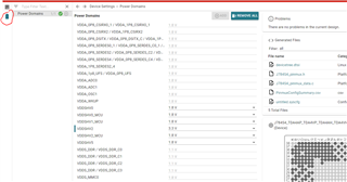
My SDK version:
        linux:  ti-processor-sdk-linux-adas-j784s4-evm-09_01_00_06 

        rtos:  ti-processor-sdk-rtos-j784s4-evm-09_01_00_06

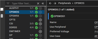
The CPSW2G pin in the native SDK package is connected to the RTL9000AA_RTL9000AN Ethernet device,

and the CPSW2G pin in our test board is directly connected to the external switch chip,

may I ask how to modify the driver to make the Ethernet connected?

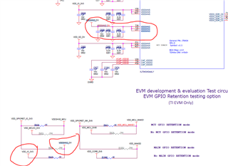
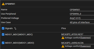
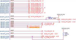
The following is a partial hardware schematic of our test board:

j784s4 side:

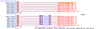
switch chip(BCM89571) side:

Above, thank you.

  • Hi,

    and the CPSW2G pin in our test board is directly connected to the external switch chip,

    Do you mean it is MAC to MAC connection.

    If so, In MAC Port node use "fixed-link" and set speed and duplex mode as shown in below.

    &main_cpsw1_port1 {
    	status = "okay";
    	phy-mode = "rgmii-rxid";
    	fixed-link {
    	      speed = <1000>;
    	      full-duplex;
    	};
    };


    Also, Make sure that RGMII Rx delay enabled from switch. As TDA4 support only configuration of Tx delay enable or not at MAC side.
    Only when phy-mode is "rgmii-id" or "rgmii-txid"  TDA4 disables the internal Tx delay, if not Tx delay is enabled at MAC side.

    Best Regards,
    Sudheer

  • Hi,

     Yes , it is MAC to MAC connection.

    I added what you provided and got a strange waveform.

    The frequency of the waveform is 125Mhz, which is expected,

    but the amplitude of the waveform is fluctuating, which is strange.

    What is your opinion on this phenomenon?

    The waveform is as follows:

    Continuously detected waveforms:

    Stopped waveform 1:

    Stopped waveform 2:

    Above, thank you

  • Sorry, this may be the hardware problem of my test board,

    I will investigate this first, thank you very much for your reply.

  • Hi,

    I will investigate this first, thank you very much for your reply.

    Sure, If you need any help please let us know.

    Best Regards,
    Sudheer

  • Hi,

    On my test board, I noticed a strange phenomenon that there seemed to be another controller controlling the SW2G_RGMII_TX clock.

        All my software is burned on an SD card,

        1. If the SD card is not inserted, the SOC cannot work properly and no log is generated over the serial port. uboot will not boot either

            1.1 When my external switch chip is working properly, there is 125M clock waveform on SW2G_RGMII_TX_CTL(PIN AF35)

            1.2 When my external switch chip does not work, there is a 2.5M clock waveform on SW2G_RGMII_TX_CTL(PIN AF35)

        What explains this phenomenon? In theory, no clock should be created.

    2. How do I disable the clock adaptive function of RGMII?

  • Hi,

    1.2 When my external switch chip does not work, there is a 2.5M clock waveform on SW2G_RGMII_TX_CTL(PIN AF35)

    2.5MHz is clock for 10Mbps link speeed.
    May be your switch is configured for SGMII and no link partner is detected and link speed fall down to 10Mbps default speed and producing the clock speed of 2.5MHz.

    2. How do I disable the clock adaptive function of RGMII?

    If you want to stop clock, disable the RGMIII interface at switch side.

    Best Regards,
    Sudheer

  • Hi,

    During the VH startup, from the power-on to the uboot, the clock is always 125M. When the Linux kernel is started, the waveform changes:

    1. When I set speed = <1000>; When the Linux kernel starts, the clock changes to a waveform with ever-varying amplitudes (top image in the earlier comment), with a clock frequency of 125Mhz and amplitudes varying between 3.3v and 1.8v.

    2. When I set speed = <100>; When the Linux kernel is started, the clock changes to the state after the superposition of the 125M and 25M frequencies.

    From the perspective of the phenomenon, before the Linux kernel started, there was a stable 125Mhz clock, but after the kernel started, an additional waveform was added, and this waveform followed my configuration.

    Looks like two waveforms superimposed.

    The expectation should be that there will always be only one waveform, and my configuration should load the original default configuration, but look like it is not overwritten, but added. 

    Can this phenomenon be explained?

    3. How to set my RGMII operating voltage?

  • Hi, 

    From where you are capturing the clock? 

    Tx click is from tda4vh ans Rx clock will be from BCM switch. 

    Do you mean you are observing the clock as per speed configuration but voltage level is 1.8 instead of 3.3v? 

    If so, can you check voltage of VDDSHV2 is 3.3 or 1.8? 

    Above should be 3.3v in order to operate Main CPSW2G in RGMII with 3.3v

    Please refer to below from sysconfig file. 

    Best regards, 

    Sudheer

  • Hi,

    I captured the clock signal on SW2G_RGMII_TX_CTL (PIN AF35) (there is a screenshot of the schematic in the problem description)

    I'm sorry, but I can't find the option in your screenshot in sysConfig, can you explain where it is?

  • Hi,

    I captured the clock signal on SW2G_RGMII_TX_CTL (PIN AF35) (there is a screenshot of the schematic in the problem description)

    Clock should be from RGMII_TXC is the clock signal of RGMII from MAC. I hope above comment would be typo as you have confirmed clock is coming as per configuration.

    Regarding the signal level, check your schematic, what is the voltage supplied to VDDSHV2 pins of TDA4VH. If supplied voltage is 3.3V then you may get output signal level as 3.3v is not it will be 1.8V.

    Please refer below, TI EVM schematic for refence. Also, find full schematic details from EVM page on ti.com


    Best Regards,
    Sudheer

  • Hi,

    Sorry, my mistake. The pin I measured was SW2G_RGMII_TXC AL34

    I have confirmed that the voltage of the VDDSHV2 pin of TDA4VH is 3.3v.

    I may not have expressed myself clearly, regarding the option to set the voltage, can you tell me in which group it is?

  • Hi,

    I may not have expressed myself clearly, regarding the option to set the voltage, can you tell me in which group it is?

    Please refer to Power Domain options form Sysconfig tool.


    I have confirmed that the voltage of the VDDSHV2 pin of TDA4VH is 3.3v.

    If so, it could be something else.
    Can you please create new thread related to HW signal Query. 

    As we addressed the SW configuration for direct MAC connection using fixed link node in device tree.

    Best Regards,
    Sudheer

  • HI

    Thank you .

    when I set VDDSHV2 pin of TDA4VH is 3.3v. There are two warnings:

  • Hi,

    when I set VDDSHV2 pin of TDA4VH is 3.3v. There are two warnings:

    This is shown in CPSW9G, as VDDSHV2 is common for CPSW9G/CPSW2G.

    In case of CPSW2G it will be for RGMII/RMII lines as well along with MDIO lines. Whereas In case of CPSW9G it will be only for MDIO lines Port Lines will be Serial Lanes from SerDes which are 1.8V. 

    As you have selected VDDSHV2 as 3.3 so, it showing conflict in CPSW9G window, This can be ignored no Issue. As CPSW9G supports 3.3V.

    Best Regards.
    Sudheer

  • Thank you very much for your support

    Best Regards.