This thread has been locked.

If you have a related question, please click the "Ask a related question" button in the top right corner. The newly created question will be automatically linked to this question.

TMS320C6678: TMS320C6678: Please consult about the SPI serial transmission speed issue!

Part Number: TMS320C6678
Other Parts Discussed in Thread: TPIC2060A

The SPI has the following features:

Up to 66 MHz operation

The manual for the Serial Peripheral Interface (SPI) for KeyStone Devices User's Guide mentioned above supports operations up to 66 MHz.
On the hardware platform of C6678, implement SPI dual bus control within a 3.3us (3300ns) interrupt cycle, and perform multiple SPI read and write data (DSP uses SPI for data transmission to TPIC2060A (35M=28.6ns) and AD/DA (48M=21ns) boards). One read and write register of the 36M SPI device is 16 (data bits)+2 (startup) * 28.6ns=514.8ns.
Encountering a problem, the theoretical calculation shows that within the interrupt cycle, 3300/515=6.4, SPI communication can be performed 6.4 times. However, in actual transmission, the interrupt cycle exceeded 2.3us (5.6us) after only 4 transmissions, and exceeded 1us (4.3) after 3 timeouts. It is estimated that 5.6-4.3=1.3us, and the usage time for one transmission is 1.3us, far exceeding 514.8ns.
SPI communication refers to TI's "7242.K1-STK_v1.1" SPI driver code:
//In the reference case, SPI communication adopts the read write synchronization method (read while writing). The function name is as follows:

Uint32 KeyStone_SPI_TxRx(Uint8 * txBuf, Uint32 firstTxByte,
Uint32 numTxByte, Uint8 * rxBuf, Uint32 firstRxByte, Uint32 numRxByte,
SPI_Transfer_Param * transfer)

Upon checking the program, it was found that the above function called KeyStone_SPI_wait_flag to delay checking the TXINTFLG and RXINTFLG states.

code:if(0==KeyStone_SPI_wait_flag(CSL_SPI_SPIFLG_RXINTFLG_MASK, CSL_SPI_SPIFLG_RXINTFLG_MASK))

#define SPI_TIMEOUT_CYCLES ((1000)*8*100)

Int32 KeyStone_SPI_wait_flag(Uint32 flag_mask, Uint32 expect)
{
Uint32 startTSC;
Uint32 delay;
volatile Uint32 flag;

startTSC= TSCL;
//flag_mask:CSL_SPI_SPIFLG_RXINTFLG_MASK
flag= gpSPI_regs->SPIFLG&flag_mask; //CSL_SPI_SPIFLG_RXINTFLG_MASK (0x00000100u)

/*Wait until SPI flag= expect value */
//1 = Transmit buffer is empty. An interrupt is pending to fill the transmitter.
while(flag!= expect)
{
/*if wait time is much larger than theoretical transfer time of
a byte, then it is looked as timeout.*/
delay= TSC_getDelay(startTSC);
// printf("KeyStone_SPI_wait_flag delay= %d \n",delay);
if(delay> SPI_TIMEOUT_CYCLES)
{
printf("KeyStone_SPI_wait_flag 0x%x timeout, SPIFLG=0x%x\n",
flag_mask, gpSPI_regs->SPIFLG);

return 0;
}
flag= gpSPI_regs->SPIFLG&flag_mask;

};

return 1;
}

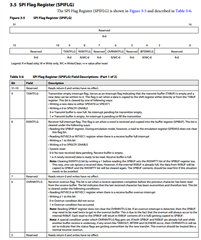
The function is used to determine TXINTFLG and RXINTFLG in SPI Flag Register (SPIFLG), where there is a delay waiting code to determine whether TXINTFLG and RXINTFLG are 1, resulting in a delay.
At first, attempts were made to modify # define SPI-TIMEOut-CYCLES (((1000) * 8 * 100) ---># define SPI-TIMEOut-CYCLES ((400) * 1 * 1), but the SPI transfer time did not change.
Furthermore, the write to TXINTFLG judgment was masked in the KeyStone_SPI-TxRx function, resulting in 4 SPI communication interruption cycles becoming 4.7us (0.9us shorter than the previous 5.6us). At this point, the two SPI control ICs read and write register data OK.
Finally, the write RXINTFLG judgment was masked in the KeyStone_SPI-TxRx function, and the interrupt cycle returned to normal 3.3us. But two SPI control ICs read register data NG, but the write data IC acted.
1. The maximum operating speed in the SPI manual is 66MHz, which means that the SPIDAT1 or SPIBUF register data conversion speed can also support up to 66MHz.
2. To ensure the correctness of SPI transmission data, do we need to check the TXINTFLG and RXINTFLG flags before reading or writing SPIDAT1 or SPIBUF registers? When writing new SPIDAT1 data from the instruction manual, TXINTFLG will be updated. Do we need to make a judgment when writing data?
3. Now that the RXINTFLG write judgment has been blocked, the interrupt cycle has returned to normal 3.3us, and the IC has acted (feels normal), which indicates that the controlled IC has read the transmission data of SPI. Can hardware circuit problems be ruled out?

  • XING CUI,

    Let me have a look at it and get back.

    Regards

    Shankari G

  • XING,

    Question:- 

     Is this function, KeyStone_SPI_wait_flag() is part of TI offerings? If yes, please specify the name of the software package and its version details.

    --

    If the CPU/core clock of C6678 is 1.2 GHz, then SPI module clock shall be 200 MHz, as per /* SYSCLK7  = CPU_Clk/6 in HZ */.

    Please check the SPI module clock derived in your board.

    --

    Please refer the SPI initialization and configuration source code given in the PROCESSOR-SDK-RTOS-C667x  06_03_00_106
    https://software-dl.ti.com/processor-sdk-rtos/esd/C667x/latest/index_FDS.html

    I have personally tested the SPI sample code enclosed in the platform test example.

    --

    I would recommend you to run that example and observe the performances and speed on TI C6678 EVM.

    And then compare the results with your setup and custom board.

    ---

    A sample SPI transfer function:


    /******************************************************************************
     * 
     * Function:    spi_xfer  
     *
     * Description: This function sends and receives 8-bit data serially
     *
     * Parameters:  uint32_t nbytes   - Number of bytes of the TX data
     *              uint8_t* data_out - Pointer to the TX data
     *              uint8_t* data_in  - Pointer to the RX data
     *              Bool terminate  - TRUE: terminate the transfer, release the CS
     *                                FALSE: hold the CS
     *
     * Return Value: error status
     * 
     ******************************************************************************/
    SPI_STATUS 
    spi_xfer
    (
        uint32_t              nbytes,
        uint8_t*              data_out,
        uint8_t*              data_in,
        Bool                terminate
    )
    {
        uint32_t          i, buf_reg;
        uint8_t*          tx_ptr = data_out;
        uint8_t*          rx_ptr = data_in;
        
        
        /* Clear out any pending read data */
        SPI_SPIBUF;
        
        for (i = 0; i < nbytes; i++) 
        {
            /* Wait untill TX buffer is not full */
            while( SPI_SPIBUF & CSL_SPI_SPIBUF_TXFULL_MASK );
            
            /* Set the TX data to SPIDAT1 */
            data1_reg_val &= ~0xFFFF;
            if(tx_ptr) 
            {
                data1_reg_val |= *tx_ptr & 0xFF;
                tx_ptr++;
            }
            
            /* Write to SPIDAT1 */
            if((i == (nbytes -1)) && (terminate)) 
            {
                /* Release the CS at the end of the transfer when terminate flag is TRUE */
                SPI_SPIDAT1 = data1_reg_val & ~(CSL_SPI_SPIDAT1_CSHOLD_ENABLE << CSL_SPI_SPIDAT1_CSHOLD_SHIFT);
            } else 
            {
                SPI_SPIDAT1 = data1_reg_val;
            }
            
            
            /* Read SPIBUF, wait untill the RX buffer is not empty */
            while ( SPI_SPIBUF & ( CSL_SPI_SPIBUF_RXEMPTY_MASK ) );
            
            /* Read one byte data */
            buf_reg = SPI_SPIBUF;
            if(rx_ptr) 
            {
                *rx_ptr = buf_reg & 0xFF;
                rx_ptr++;
            }
        }
        
        return SPI_EOK;
        
    }

    A sample SPI initialization and configuration:-

    /******************************************************************************
     * 
     * Function:    spi_claim  
     *
     * Description: This function claims the SPI bus in the SPI controller 
     *
     * Parameters:  Uint32 cs       - Chip Select number for the slave SPI device
     *              Uint32 freq     - SPI clock frequency  
     *
     * Return Value: error status
     * 
     ******************************************************************************/
    SPI_STATUS 
    spi_claim
    (
        uint32_t      cs,
        uint32_t      freq
    )
    {
        uint32_t scalar;
    
        PLIBSPILOCK()
    
        /* Enable the SPI hardware */
        SPI_SPIGCR0 = CSL_SPI_SPIGCR0_RESET_IN_RESET;
        spi_delay (2000);
        SPI_SPIGCR0 = CSL_SPI_SPIGCR0_RESET_OUT_OF_RESET;
    
        /* Set master mode, powered up and not activated */
        SPI_SPIGCR1 =   (CSL_SPI_SPIGCR1_MASTER_MASTER << CSL_SPI_SPIGCR1_MASTER_SHIFT)   |
                        (CSL_SPI_SPIGCR1_CLKMOD_INTERNAL << CSL_SPI_SPIGCR1_CLKMOD_SHIFT);
        
        
        /* CS0, CS1, CLK, Slave in and Slave out are functional pins */
        if (cs == 0) {
            SPI_SPIPC0 =    (CSL_SPI_SPIPC0_SCS0FUN0_SPI << CSL_SPI_SPIPC0_SCS0FUN0_SHIFT) |
                            (CSL_SPI_SPIPC0_CLKFUN_SPI << CSL_SPI_SPIPC0_CLKFUN_SHIFT)     |
                            (CSL_SPI_SPIPC0_SIMOFUN_SPI << CSL_SPI_SPIPC0_SIMOFUN_SHIFT)   |
                            (CSL_SPI_SPIPC0_SOMIFUN_SPI << CSL_SPI_SPIPC0_SOMIFUN_SHIFT);
        } else if (cs == 1) {
            SPI_SPIPC0 =    ((CSL_SPI_SPIPC0_SCS0FUN1_SPI << CSL_SPI_SPIPC0_SCS0FUN1_SHIFT) |
                            (CSL_SPI_SPIPC0_CLKFUN_SPI << CSL_SPI_SPIPC0_CLKFUN_SHIFT)     |
                            (CSL_SPI_SPIPC0_SIMOFUN_SPI << CSL_SPI_SPIPC0_SIMOFUN_SHIFT)   |
                            (CSL_SPI_SPIPC0_SOMIFUN_SPI << CSL_SPI_SPIPC0_SOMIFUN_SHIFT)) & 0xFFFF;
        }
        
        /* setup format */
        scalar = ((SPI_MODULE_CLK / freq) - 1 ) & 0xFF;
    
        if ( cs == 0) {
            SPI_SPIFMT0 =   (8 << CSL_SPI_SPIFMT_CHARLEN_SHIFT)               |
                            (scalar << CSL_SPI_SPIFMT_PRESCALE_SHIFT)                      |
                            (CSL_SPI_SPIFMT_PHASE_DELAY << CSL_SPI_SPIFMT_PHASE_SHIFT)     |
                            (CSL_SPI_SPIFMT_POLARITY_LOW << CSL_SPI_SPIFMT_POLARITY_SHIFT) |
                            (CSL_SPI_SPIFMT_SHIFTDIR_MSB << CSL_SPI_SPIFMT_SHIFTDIR_SHIFT);
        }else if ( cs == 1) {
            SPI_SPIFMT0 =   (16 << CSL_SPI_SPIFMT_CHARLEN_SHIFT)               |
                            (scalar << CSL_SPI_SPIFMT_PRESCALE_SHIFT)                      |
                            (CSL_SPI_SPIFMT_PHASE_NO_DELAY << CSL_SPI_SPIFMT_PHASE_SHIFT)     |
                            (CSL_SPI_SPIFMT_POLARITY_LOW << CSL_SPI_SPIFMT_POLARITY_SHIFT) |
                            (CSL_SPI_SPIFMT_SHIFTDIR_MSB << CSL_SPI_SPIFMT_SHIFTDIR_SHIFT);
        }
        
        /* hold cs active at end of transfer until explicitly de-asserted */
        data1_reg_val = (CSL_SPI_SPIDAT1_CSHOLD_ENABLE << CSL_SPI_SPIDAT1_CSHOLD_SHIFT) |
                        (0x02 << CSL_SPI_SPIDAT1_CSNR_SHIFT);
         if (cs == 0) {
             SPI_SPIDAT1 =   (CSL_SPI_SPIDAT1_CSHOLD_ENABLE << CSL_SPI_SPIDAT1_CSHOLD_SHIFT) |
                             (0x02 << CSL_SPI_SPIDAT1_CSNR_SHIFT);
         } 
    
        /* including a minor delay. No science here. Should be good even with
        * no delay
        */
        if (cs == 0) {
            SPI_SPIDELAY =  (8 << CSL_SPI_SPIDELAY_C2TDELAY_SHIFT) |
                            (8 << CSL_SPI_SPIDELAY_T2CDELAY_SHIFT);
            /* default chip select register */
            SPI_SPIDEF  = CSL_SPI_SPIDEF_RESETVAL;        
        } else if (cs == 1) {    
            SPI_SPIDELAY =  (6 << CSL_SPI_SPIDELAY_C2TDELAY_SHIFT) |
                            (3 << CSL_SPI_SPIDELAY_T2CDELAY_SHIFT);
        }
        
        /* no interrupts */
        SPI_SPIINT0 = CSL_SPI_SPIINT0_RESETVAL;
        SPI_SPILVL  = CSL_SPI_SPILVL_RESETVAL;
    
        /* enable SPI */
        SPI_SPIGCR1 |= ( CSL_SPI_SPIGCR1_ENABLE_ENABLE << CSL_SPI_SPIGCR1_ENABLE_SHIFT );
    
        if (cs == 1) {
            SPI_SPIDAT0 = 1 << 15; 
            spi_delay (10000);        
            /* Read SPIFLG, wait untill the RX full interrupt */
            if ( (SPI_SPIFLG & (CSL_SPI_SPIFLG_RXINTFLG_FULL<<CSL_SPI_SPIFLG_RXINTFLG_SHIFT)) ) {                
                /* Read one byte data */
                scalar = SPI_SPIBUF & 0xFF;
                /* Clear the Data */
                SPI_SPIBUF = 0;
            }
            else {
                /* Read one byte data */
                scalar = SPI_SPIBUF & 0xFF;
                return SPI_EFAIL;
            }
        }
        return SPI_EOK;
    }
    

    Please compare the configuration with your code....

    Regards

    Shankari G

  • Hi,Shankari G

    7242.K1_STK_v1.1.zip

    The code should have been written by Brighton Feng.

    The operating frequency of DSP C6678 is 1GHz.

    Thank you for providing a case study.
    In the case, when sending data, we will wait for the SPI_SPIBUF_TXFULL buffer to be not full, and when receiving data, we will wait for the SPI_SPIBUF_RXEMPTY buffer to be empty.
    1. The transmission has timed out now, it should be waiting for SPIBUF update time. What is the update speed of this SPIBUF data?
    2. May I inquire if it is possible to read (SPIDAT1) or write (SPIBUF) through the breakpoints in SPI-SPIFLG-RXINTFLG and SPI-SPIFLG-TXINTFLG?
    3. What may be the reason for the slow changes in RXINTFLG and TXINTFLG positions?

  • XING,

    Right now, for C6678 device, the latest supported software package is processor SDK 6.3 ( I have provided the link in my previous post).

    My question is not the name of the author but the name of the software package and its version.

    --

    For the rest of your questions, let me look at it and get back.

    Regards

    Shankari G 

  • Hi Shankari G , 

    The SPI transmission timeout now is likely caused by waiting for the TXFULL and RXEMPTY flags of SPIBUF to update.

    The program does not wait for TXFULL bit changes, but directly writes SPIDAT1 to the device, and the device also operates normally, reducing the transmission time. But without checking the RXEMPTY flag, the device register data reading SPIBUF data is abnormal.

    What is the maximum frequency of TXFULL and RXEMPTY in the DSP SPI register? What could be the reason for its slowing down?

  • XING,

    The max frequency cannot be for the registers. The max frequency shall be for the SPI modules.

    For example:- 

    If the DSP core frequency is 1.2 GHz, then, SYSCLK7 ---> ( 1.2 GHz / 6 ) = 200000000 Hz = 200 MHz ----> The max frequency for SPI module.

    • SYSCLK7: 1/6-rate clock for slow peripherals (GPIO, UART, Timer, I2 C, SPI, EMIF16, etc.) and sources the SYSCLKOUT output pin.

    Regards

    Shankari G

  • Hi Shankari G , 

    Thank you very much for your reply.
    Do you understand the content in your reply correctly?
    The working frequency of the SPI module is provided by SYSCLK7. If my DSP is set to 1GHz, the SPI module frequency of 1G/6 is approximately equal to 166M
    Does the SPI related register update data also reach 166MHz?

  • XING,

    What is the maximum frequency of TXFULL and RXEMPTY in the DSP SPI register? What could be the reason for its slowing down?

     -----> your question is not understandable...

    -------> What do you mean by the max frequency of TXFULL and RXEMPTY?

    ---

    As far as I know, the value of the DSP SPI BUFF register  -  TXFULL can have value only '0' or '1'.

    --

    Extract from - https://www.ti.com/lit/ug/sprugp2a/sprugp2a.pdf

    --

    29th bit -  TXFULL - Transmit data buffer full.

    This flag is a read-only flag. Writing into SPIDAT0 or SPIDAT1 field while the TX shift register is full will automatically set the TXFULL flag. Once the data is copied to the shift register, the TXFULL flag will be cleared. Writing to the SPIDAT0/SPIDAT1 register when both TXBUF and the TX shift register are empty does not set the TXFULL flag.

    0 = The transmit buffer is empty; SPIDAT0/SPIDAT1 is ready to accept a new data.

    1 = The transmit buffer is full; SPIDAT0/SPIDAT1 is not ready to accept a new data

    --

    31th bit -  RXEMPTY - Receive data buffer empty.

    When the host reads the SPIBUF field or the whole SPIBUF register, this will automatically set the RXEMPTY flag. When a data transfer is completed, the received data is copied into SPIBUF, the RXEMPTY flag is cleared. This flag is set to 1 under following conditions: • Reading the RXDATA portion of the SPIBUF register. • Writing 1 to clear the RXINTFLG bit in SPIFLG register.

    0 = New data has been received and copied into the SPIBUF register.

    1 = No data received since last reading of SPIBUF register.

    Write-clearing the SPIFLG.RXINTFLG bit before reading the SPIBUF indicates the received data is being ignored. Conversely, SPIFLG.RXINTFLG can be cleared by reading the RXDATA portion of the SPIBUF register or the entire SPIBUF register.

    Regards

    Shankari G